question

dsorrel avatar image
dsorrel asked

Smart Shunt Installation Options

I have an existing Victron System in my RV. Lynx 1000 Distribution, Lynx 1000 Shunt, Lynx Power in 1000. Multiplus 24v/3000 va, two MPPT 150/160, Orion DC/DC 24/12, color contol GX.

I want to add a BuckBoost 12/24 DC-DC 50 A converter to use the second alternator in my vehicle to charge the 24v batteries when driving.

1. I am not sure where to add the 24v buck boost input. I think to the Lynx 1000 power in. (no room in the Lync 1000 Distribution).

2. I would use a smart shunt 500 to measure current and read data to the Color Control GX. But the buck boost uses a common ground between the 12/24v. The shunt is connected to the ground. I am not sure what current it would be measuring?

2. I would like to add the smart shunt to the Color Control GX. The Color Control GX has two VE.direct inputs and both are used. I assume I can use the VE.direct to usb interface?

Regards,

David

SmartShunt
2 |3000

Up to 8 attachments (including images) can be used with a maximum of 190.8 MiB each and 286.6 MiB total.

5 Answers
pwfarnell avatar image
pwfarnell answered ·

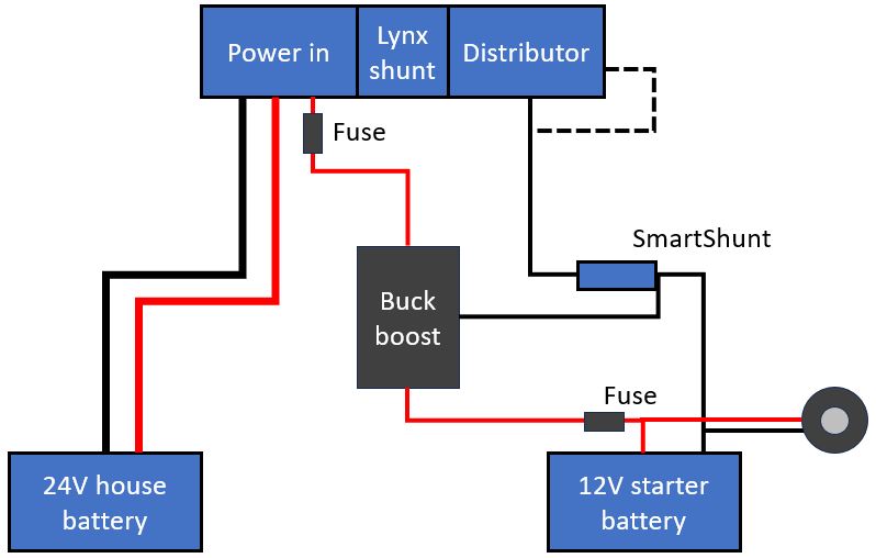
@dsorrel I think the attached sketch will work and allow use of the Power in. The location of the shunts will keep the battery monitoring correct and the DC loads calculation in the CCGX.

1. Yes you could use the power in for the +ve connection as long as you fuse it on the output. However, you do need to use the distributor for the negative wire from the starter battery. If you use the power in for the starter battery negative Lynx Shunt will not measure the charge current going to the second battery and your SOC will get out of step. Some people have made a small hole in the right hand side of the distributor and connected to the end of the -ve busbar or you could use the ground post on the distributor. If your starter battery does not connect to the distributor but goes to the chassis and then you have a chassis ground to the distributor then you need to connect the SmartShunt between the starter battery negative and the ground connection and still have the buck-boost negative where shown.

2. The attached diagram shows where to install the SmartShunt so that it measures the charge current going in to your house battery. It is important to have the buck-boost negative on the starter battery side of the shunt which will be the "System -ve" terminal on the shunt. The "Battery -ve" terminal on the shunt connects to the distributor. The current flow from the alternator/ starter battery will be about twice what is measured by the SmartShunt.

3. Yes, you need a VE Direct to USB cable.

buck-boost.jpg


buck-boost.jpg (39.3 KiB)
2 |3000

Up to 8 attachments (including images) can be used with a maximum of 190.8 MiB each and 286.6 MiB total.

dsorrel avatar image
dsorrel answered ·

Thank you. The shunt and the ve direct to USB are odered and will be here tomorrow. Now I understand how the currents are flowing. The distributer Ve- is open on the top. I took it all apart today. So that is an easy connection. The Power in has open Ve+ terminals. I have the fuses to protect the system.

I assume when I hook it all up I will need to program Color Control GX to know what current the Shunt is measuring? Do I need adjust setting in anything else?

Thanks again for your help.

David

1 comment
2 |3000

Up to 8 attachments (including images) can be used with a maximum of 190.8 MiB each and 286.6 MiB total.

pwfarnell avatar image pwfarnell commented ·

@dsorrel you program the shunt, you set it as a DC energy meter (default is battery monitor) and then choose a sub type, I can not remember them all, one is probably generic DC load, read the manual it will tell you, but it needs to be a load type. The only thing on the CCGX is to make sure "has DC system" is active in the system setup menu. The new SmartShunt will be shown on the device list and recorded to VRM automatically.

0 Likes 0 ·
dsorrel avatar image
dsorrel answered ·

@pwfarnell I have the shunt and the 50A buck boost installed and partially hook up. I configured the buck boost and the shunt. I set it up as a DC energy meter. I believe I set it up as you showed in the diagram. I connected system minus to the distributer Ve- termina and the Battery Minus to the Buck Boost negative and Starter Battery negative. In general I believed the camper ground and vehicle grounds are separate. But maybe not. The only wire with ground from the truck to the camper are the trailer connections to power road lighting on the camper.

I turned power on and I show a 10 to 12 amp draw through the shunt. If I disconnect the chassis ground this goes away. So there is some leakage somewhere. But connecting and disconnecting power leads does not produce any spark. I would think at 26 V 12 amp there would be sparks.

There are not other wiring between the truck and camper but there is metal turnbuckles that connect to hard points between the two. The frame on the camper may be a ground as well.

In any case I don't know what is using this 12 amps. I tried to calibrate the shunt to zero as shown in the manual but it only drops the idle amperage to about 8 amps. I dont think is is a good idea to run it without the chassis ground. It does not make good electrical practice to me.

Any suggestions.?

1 comment
2 |3000

Up to 8 attachments (including images) can be used with a maximum of 190.8 MiB each and 286.6 MiB total.

pwfarnell avatar image pwfarnell commented ·

1. Thinking about this some more, the SmartShunt needs to be set up as a Generic source because that is what you are using it to measure, charge going into the 24V battery.

2. Your set up seem more complex than expected, the camper is obviously separate to the vehicle somehow, something I am not familiar with as this type of item is not common here in the UK. If the current is measured with the chassis ground connected but not with it disconnected then yes you have some other current draws but without wiring diagrams it is hard to diagnose.


0 Likes 0 ·
dsorrel avatar image
dsorrel answered ·

The system also includes an Orion 24/12-70 This is non isolated. This supplies all 12 V to the camper. I am wondering is this, the 24V ground and Chassis ground are interacting/leaking. I will research and track some things down today.

As I said the Smart Shunt read out was showing 8-12 amps without the buckboost engaged but the chassis ground attached. But no "sparks" or arcing was present when I connected or disconnected the ground. This seems strange to me.

2 |3000

Up to 8 attachments (including images) can be used with a maximum of 190.8 MiB each and 286.6 MiB total.

dsorrel avatar image
dsorrel answered ·

I believe I have the buck boost wiring set up better. The shunt is showing zero current when the buck boost is off. However, the Color GX is not showing batter state of charge any more. I believe I need to reconfigure something. Any ideas?

When operating, the Color GS has an icon "DC Power" Generally this shows what the orion DC-DC converter is powering. Now it seems to add or subtract what ever the Smart Shunt is showing, i.e. if the buck boost is giving current. So, I believe the system is grouping the smart shunt with the Orino DC-DC converter. (24v to 12V).

1 comment
2 |3000

Up to 8 attachments (including images) can be used with a maximum of 190.8 MiB each and 286.6 MiB total.

pwfarnell avatar image pwfarnell commented ·
With 2 shunts in the system you may need to specifically choose the Lynx shunt as the battery monitor in Settings> System setup, this is the only reason I can think of for the SOC disappearing. There have been some issues that some measurements by a SmartShunt in energy meter mode are not being added or subtracted properly up by the DC box. If you have it as a generic load, try it as a generic source to see if the maths gets any better. I believe gui2 will be better in this regard.
0 Likes 0 ·