question

garethcurtis avatar image
garethcurtis asked

ESS grid parallel with AC Socket connected directly to AC Out 1 on Multiplus II

Hi,

I recently posted questioning about how my electrician wired up the ET340 energy meter as it didn't work (he didn't connect the neutral to it). Now I'm questioning about something else he did. He said it was ok to wire an AC socket directly to the AC OUT 1 on the Multiplus II. I said does it need to go through something and he said no. I'm not an electrician, as you can tell, but I would have thought it might need to have something between the socket and the inverter?

My aim is to use the ESS and feedback the power from the batteries to the house via AC IN which I saw that @Sean said his does? Though I must admit, I still don't know how it does this. Why would it pull battery power rather than the grid, if the Multiplus is not sitting between the grid and the consumer unit. I know it says about using the meter to try to keep grid input at zero or thereabouts but how does it actually stop power flowing from the grid? If the grid is still directly connected to my consumer unit.

On the AC out, I just want to plug in my large freezer so it's continually powered if the grid goes hence the extra socket directly wired to the inverter..

Sorry quite a few questions there in the end.

Please can anyone offer any advice?

Thanks.
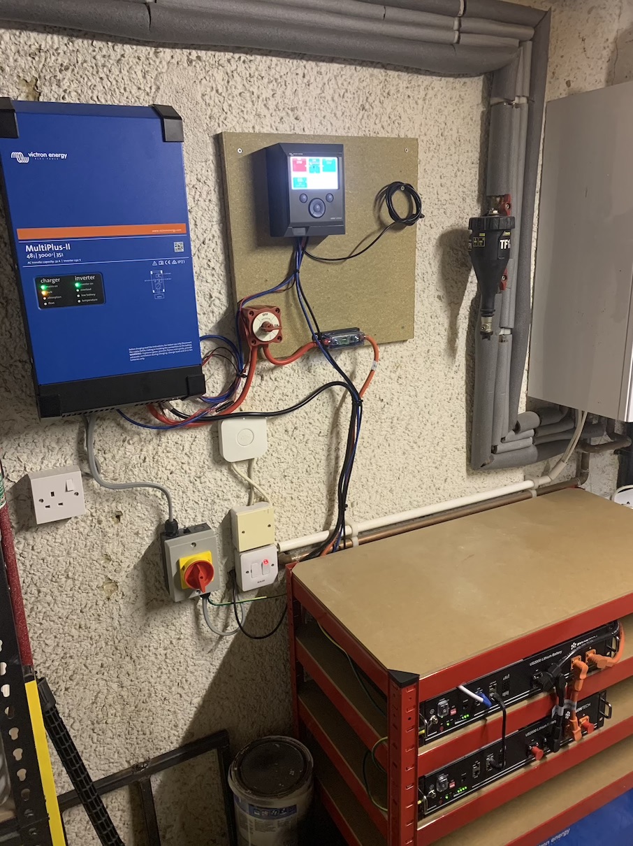

ESS
img-5180.jpg (361.9 KiB)
2 |3000

Up to 8 attachments (including images) can be used with a maximum of 190.8 MiB each and 286.6 MiB total.

3 Answers
Rob Duthie avatar image
Rob Duthie answered ·

Hi

Yes it does on AC1 out put as that is the back supply in case of grid failure. These are bidirectional inverters, power can flow in either direction. In ESS mode it can, you can set it up to import and export power at will.

There should be RCD between the inverter and power socket for safety reasons. Not sure what the UK wiring rules are.

Do you have PV panels connected, or just using the grid to charge off peak etc?

But In NZ yes.


Regards

Rob D

NZ

2 |3000

Up to 8 attachments (including images) can be used with a maximum of 190.8 MiB each and 286.6 MiB total.

garethcurtis avatar image
garethcurtis answered ·

Thanks @Rob Duthie ok, good to know it is definitely bi-directional. Correct, I'm just using time of use tariff at the moment to charge the batteries from the grid overnight but plan to add PV soon too....

Interesting re RCD between inverter and power socket; maybe I'll add one myself as I don't really know how I can tell him I think he should do it :D Like me telling him how to do his job. Though obviously he didn't do the energy meter quite right either, and is coming back next week to fix that!

Thanks again.

3 comments
2 |3000

Up to 8 attachments (including images) can be used with a maximum of 190.8 MiB each and 286.6 MiB total.

There are many electricians around, you should find one whom you feel confident in their experience and workmanship.

Those on this list should be able to refer you on to an installer who is familiar with this equipment and it’s requirements in your area: https://www.victronenergy.com/where-to-buy

0 Likes 0 ·
garethcurtis avatar image garethcurtis Guy Stewart (Victron Community Manager) ♦♦ commented ·

Actually I really struggled to find someone. Regular electricians didn't seem to be interested and those in the renewables industry wanted to sell me 'their' whole installation, and the whole installation was around £10k-£15k. Which I don't have. Hence me trying to do it bit by bit.

0 Likes 0 ·
Rob Duthie avatar image Rob Duthie commented ·

Hi Gareth

Once you add the PV panels then you would be self sufficient, as the ESS system works well if you size everything correctly.

As the PV during the day will supply the loads in the house first and any extra goes into the battery bank, and if any left over goes into the grid. So it will run as neutral feed system if need be, you change it so it can export a certain value back into the grid from zero power to the maximum power of the inverter ratings.

And still have the AC1 output as a backup in case of a power cut.


Regards

Rob D

NZ


Reg Electronics engineer & Electrician

0 Likes 0 ·
bm97ppc avatar image
bm97ppc answered ·

BTW, from that photo it looks like your batteries are incorrectly wired. On the feed to the invertor the positive should come from the top of the stack and the negative from the bottom of the stack (or the opposite) but not from just the top (or just the bottom). If you do feed it like it is the batteries are unevenly used (unbalanced). The top battery will be over worked and the bottom battery underworked. This will cause premature failure of the top battery in your case.

Regards

Piers

2 |3000

Up to 8 attachments (including images) can be used with a maximum of 190.8 MiB each and 286.6 MiB total.