question

Wietse Wind avatar image
Wietse Wind asked

MultiPlus II setup: Cerbo L3 amps significantly differ from clamp measured amps.

Hi,

I have a three phase MultiPlus II 48/15000 setup, with two MultiPlus II units in parallel per phase. So: 3x 2 times a MPII 48/15000.

The system is working great, combined with 180kWh storage (Pylontech 36x US5000) we can greatly exceed the grid capacity of 3x50A.

However, when maxing the setup, either by charging the batteries at max. grid capacity, or max. dumping back to grid from the batteries, L3 is staying behind in Watts, Amps.

I have a VM-3P75CT at the grid side, and I noticed something was off. When maxing, this is what it looks like (see L3 vs L1 and L2):

1720182329463.png

As you can see L3 doesn't max.

However, if you look at what the MPIIs for L3 report themselves, it thinks it's maxing:
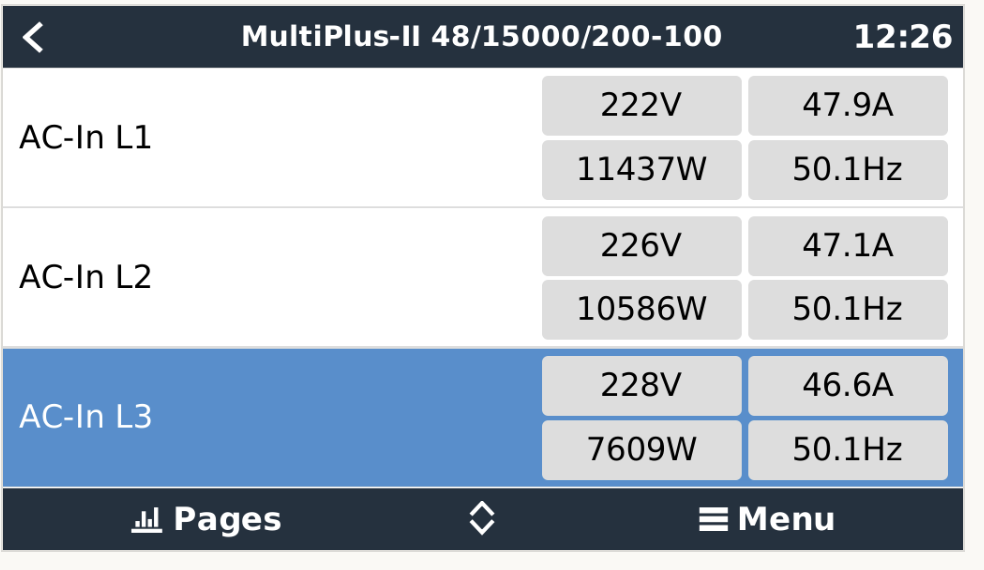
1720182370859.png

So my first thoughts were:

- Maybe the VM-3P75CT is faulty
- Maybe a configuration problem @ MPII two at L3
- Maybe the VM-3P75CT connected current clamp on L3 is faulty / not properly installed
- Something with an insane power factor (AC? Pump? shut both off, issues persists)
- Let's measure

Swapped the VM-3P75CT: same. Swapped the clamps: same. Shut the AC & pump: same. Checked the configuration for all the MPIIs in VE Configure: same (AC current limit 25A per MPII, no dynamic current limiter)

Measure:

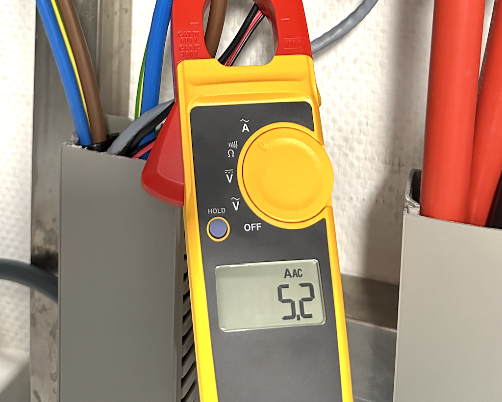
Grid to AC busbar L3:

1720183816741.png
Busbar L3 to MPII one:

1720183810638.png

Busbar L3 to MPII two:

1720183803613.png


Things I found and made sure to check (but check out):

- The MPIIs are all the same hardware generation
- The AC cabling is the same size & length between AC busbar & MPIIs
- The voltage on L3 form grid is higher. I raised the inverter set voltage to 240 to increase delta, but no change.

So L3 is running almost at half capacity. I hope someone here has an idea... As I feel all next steps are quite extreme (re-wiring, replacing MPII, etc.)

That is mind boggling to me is the fact that the system itself reports maxed amps on L3. So really the only thing that makes sense to me at this point would be that the MPII two on L3 has a faulty current meter, and thinks it's maxing (so it caps out not to exceed the configured 25A per MPII per phase), wile it isn't?

Another interesting finding is that, if I use VEConfigure to change the max amps on L3 one to say 15A, and L3 two to 35A, I get the same thing with the new limits. MPII "L3 one" is doing all the work (maxing), and "L3 two" is barely doing anything.

Which suggests a problem with "L3 two", right?

1720185570442.png

Yours,
Wietse


Multiplus-IImultiplus in parallelamps
1720182329463.png (42.1 KiB)
1720182370859.png (90.8 KiB)
1720183803613.png (1.5 MiB)
1720183810638.png (2.0 MiB)
1720183816741.png (583.3 KiB)
1720185570442.png (42.8 KiB)
2 |3000

Up to 8 attachments (including images) can be used with a maximum of 190.8 MiB each and 286.6 MiB total.

3 Answers
Duivert NL avatar image
Duivert NL answered ·

Great to hear ist solved!

2 comments
2 |3000

Up to 8 attachments (including images) can be used with a maximum of 190.8 MiB each and 286.6 MiB total.

Wietse Wind avatar image Wietse Wind commented ·
I wish, it lasted only a few minutes and then went right back to its old behaviour :(
0 Likes 0 ·
Duivert NL avatar image Duivert NL Wietse Wind commented ·

Oh thats sad to hear..

0 Likes 0 ·
Matthias Lange - DE avatar image
Matthias Lange - DE answered ·

It's not officially supported to be connected in parallel:

1720191678557.png


1720191678557.png (19.7 KiB)
7 comments
2 |3000

Up to 8 attachments (including images) can be used with a maximum of 190.8 MiB each and 286.6 MiB total.

Wietse Wind avatar image Wietse Wind commented ·

Is it?
https://qj3vjxb.dlvr.cloud/pasted_2.png

Also: this works just fine on L1 and L2.

It's only the second unit on L3 that misbehaves, reports doing half, 25A (out of 50A), while in fact does hardly anything at all.

0 Likes 0 ·
nickdb avatar image nickdb ♦♦ Wietse Wind commented ·

It is not supported, if you are off grid and you use the new external transfer switch it is supported but you cannot parallel 8k or above units grid-attached.

You will likely weld the relays in no-time, your supplier should have been able to explain this to you.

From the manual:

4.5.7. Parallel connection

Up to six identical units, with the exception of the 8k, 10k or 15k units, can be connected in parallel. When connecting inverter/charger units in parallel, the following requirements must be met:

0 Likes 0 ·
Fideri avatar image Fideri Wietse Wind commented ·
Look for similar threads here. Some manuals had errors. I suspect that's what you quoted. The errors in the manuals have since been fixed.

F.

0 Likes 0 ·
nickdb avatar image nickdb ♦♦ Fideri commented ·

This addition was made quite a while ago. Any recent equipment would be correct.

This is more likely a case of random googling linking to the wrong, or old document.

Old docs were also purged from the victron site some time back to avoid errant searches showing the wrong version.

In any case, reading a spec sheet that details it is unsupported, then assuming it is wrong is a poor call, and should have raised a red flag to ask a qualified expert, not uncle Google.

0 Likes 0 ·
Wietse Wind avatar image Wietse Wind nickdb ♦♦ commented ·
I did not mean to deny a potential change in information since I last obtained it. And I appreciate the heads up: I will obviously contact the dealer & Victron to discuss the implications.


This however does not change the fact that, at the time of purchase and installation, this was not yet known. Which means I'm running for ~two years with a setup that does in fact feature a three phase dual (parallel) setup. Significantly over dimensioned, so I guess that would help not melting any individual device.

But yes, I will make sure to inquire and take appropriate action.

It does not change the fact that there's something weird going on with just one MPII on just one phase.

0 Likes 0 ·
Matthias Lange - DE avatar image Matthias Lange - DE ♦ Wietse Wind commented ·
When did you bought/installed the system?

This limitation is in the datasheet/manual for a very long time, not just for a few months.

0 Likes 0 ·
Wietse Wind avatar image Wietse Wind Matthias Lange - DE ♦ commented ·
Over two years ago.
0 Likes 0 ·
Wietse Wind avatar image
Wietse Wind answered ·

Update: did some more digging (below), and I think I managed to narrow down where to look for a problem.

Note: it has been brought to my attention that, since obtaining and installing my current setup of 3x 2x (parallel) MP2's, it is no longer supported (or now communicated it never was) to run the larger MP2's in parallel setup. Fact is my setup was installed before this was known & communicated. I will inquire and take action. This does not change the fact that one MP2 on one phase seems to be behaving weird.

I'd still like to know if people here agree with my diagnosis & conclusions.

Core of the problem, I believe:

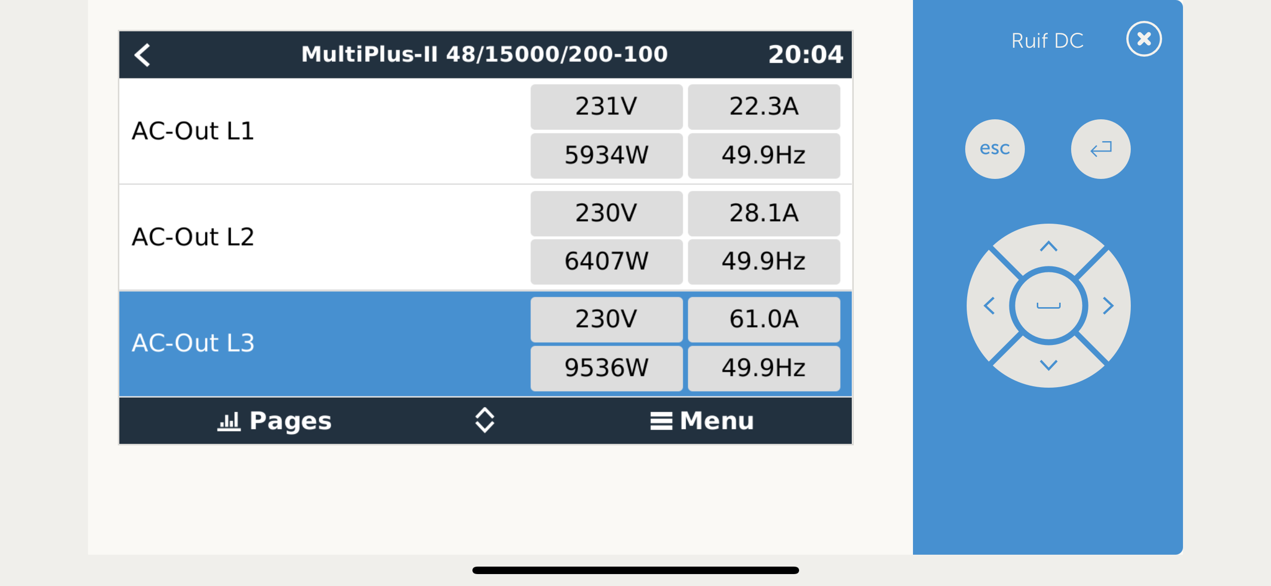
Running on batteries only (off grid), purely looking at AC Out:

1. Cerbo reports 61A on L3 (much higher than the other phases, without any reason for it to be that much higher - load is pretty evenly distributed across phasesimg-7583.png2. AC Out on L3 one: img-7584.jpeg

3. AC Out on L3 two:

img-7585.jpeg

As this is measured straight after exiting the MP2, and as this is on batteries only, I cannot draw any other conclusion than that the value reported by the MP2 "L3 two" is simply wrong?

And if you compare with the other phases, considering the same voltage (see screenshot from Cerbo) the Wattage is say +50%, which in Amps compared to the other phases would mean 11+30A is way more likely than the reported 61A - there's nothing with a shitty power factor on line.

(Heat cam does not suggest that it's doing anything more or less than the others - https://gukmnxa.dlvr.cloud/IMG_7586.jpeg)


img-7583.png (236.5 KiB)
img-7584.jpeg (1.5 MiB)
img-7585.jpeg (1.6 MiB)
9 comments
2 |3000

Up to 8 attachments (including images) can be used with a maximum of 190.8 MiB each and 286.6 MiB total.

nickdb avatar image nickdb ♦♦ commented ·
It has always been known to be unsupported. The shared manual between models did not explicitly repeat the limitation. That was corrected a long time ago as well.

In any case, your supplier should have warned you if they knew you intended paralleling them - unless it was bought online. If they said this is possible then they need to remedy the situation.

0 Likes 0 ·
nickdb avatar image nickdb ♦♦ commented ·
If there is such a measured disparity on AC between parallel inverters then something is off in the wiring. They should be within a few % of each other.

But as mentioned, unsupported. Those units will not last in that configuration, so running into problems now is not a surprise. Running them with such a difference means wear is not even either, which also makes things worse.

There isn't going to be any support for what you are doing. Please get hold of your supplier.

0 Likes 0 ·
Wietse Wind avatar image Wietse Wind nickdb ♦♦ commented ·

Thanks. Just installed external Victron current sensor which results in the same, so that eliminates a problem with the internal current sensor. AC wiring length it is, although I was assured by the electrical engineer that they are equal length - I guess not. It's already suspect that the one misbehaving is the farthest away from the AC bus. So either hardware fault or wiring are the only options left.

Regarding parallel operation: will do. Pretty screwed up situation. Just to make sure, as you seem to know more than the supplier - based on current product sheet, still online today, is my interpretation correct hat 12 pc. of Quattro 48/10000 are supported in a 4x parallel 3 phase setup? Because I would consider switching to that then (instead of 3x3 48/15000, for the sake of available space (depth)).

0 Likes 0 ·
nickdb avatar image nickdb ♦♦ Wietse Wind commented ·

Hi, no issue paralleling the quattros, big or small.


Virtually unlimited power thanks to parallel operation

Up to 6 Quattro’s can operate in parallel. Six units 48/10000/140, for example, will provide 54 kW / 60 kVA output power and 840 Amps charging capacity.

Three phase capability

Three units can be configured for three-phase output. But that’s not all: up to 6 sets of three units can be parallel connected to provide 162 kW / 180 kVA inverter power and more than 2500 A charging capacity.

Some additional limits:

Maximum System size

Three phase systems

Using our 15kVA Quattros, the maximum system size is a 180kVA three phase system. Which then consists of four units on each of the three phases: 12 units in total.

When using smaller models, there is a maximum of five units in parallel, on each of the three phases: 15 units in total. For example, using 10kVA Quattros, the maximum system size is a 150kVA three phase system.

Single phase systems

This is the same as above, but then per phase:

  • maximum single phase system with 15kVA Quattros is 75kVA: five units.

  • maximum single phase system with 10kVA Quattros is 60kVA: six units.

1 Like 1 ·
Wietse Wind avatar image Wietse Wind nickdb ♦♦ commented ·

Then that's what I'll do. And triple checking cable length. That should solve the issue in this post too. Live and learn.

Thanks!

0 Likes 0 ·
Show more comments
Fideri avatar image Fideri commented ·

I'm not qualified to give any support, just a suggestion. Why don't you run the inverter you believe to be problematic temporarily in stand alone mode and factor your findings in your decisions?

F.

0 Likes 0 ·
Wietse Wind avatar image Wietse Wind Fideri commented ·
Yeah that's what I'll do. I'll take the system back to single unit per phase, then remove the secondary ones and test them one by one. Then to replace the entire build by Quattro's. Challenges :D
0 Likes 0 ·