question

cookinwitdiesel avatar image
cookinwitdiesel asked

ESS Assistant configuration with Lynx Smart BMS

What is the correct setting for the Inverter/Charger ESS Assistant configuration when using a Lynx Smart BMS connected to the GX system with VE.CAN? I was previously using a VE.BUS BMS which is obvious how to configure but am transitioning the installation to a Lynx Smart BMS and will need to reprogram the inverters (I assume).

I also am not 100% clear on what (if anything) I need to do with the old VE.BUS BMS Mains Detector that was part of the original design.
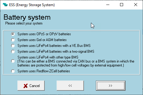
1720125842119.png

Thanks!

ESSBMSlynx bms
1720125842119.png (12.9 KiB)
2 |3000

Up to 8 attachments (including images) can be used with a maximum of 190.8 MiB each and 286.6 MiB total.

1 Answer
Stefanie (Victron Energy Staff) avatar image
Stefanie (Victron Energy Staff) answered ·

Hi @cookinwitdiesel
Since the Lynx Smart BMS is a CAN-bus (VE.Can) based BMS, you must check the box 'System uses LiFePo4 with other type BMS'.

The mains detector is no longer needed. If this simplifies installation, you can leave it connected to AC but then disconnect the VE.Bus cable between the mains detector and the MultiPlus.

2 comments
2 |3000

Up to 8 attachments (including images) can be used with a maximum of 190.8 MiB each and 286.6 MiB total.

cookinwitdiesel avatar image cookinwitdiesel commented ·
Perfect, thanks!
0 Likes 0 ·
cookinwitdiesel avatar image cookinwitdiesel cookinwitdiesel commented ·

I have ran into a snag. The inverters will not come on at all (no LEDs or communication on VE.BUS) unless the VE.BUS BMS is connected to them. To get that happy, we split the battery bank so that one battery set of BMS wires goes to the ve.bus bms and the rest go to the Lynx Smart BMS. We then connected the ve.bus bms back to the MultiPlus group (6x inverters, 3 per line in a split-phase 180 layout). Once this was done, now the inverters will turn on and communicate to the Cerbo GX however there are a couple problems.

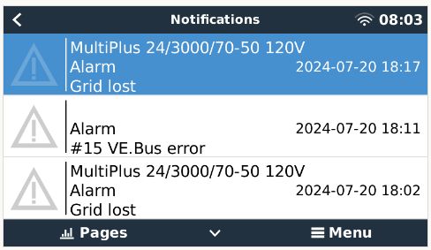
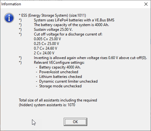
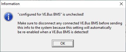
1) On the Cerbo we get a constant loop of Grid Lost and then #15 VE.Bus Error alarms. I assume the 2 are related and will focus on the #15 - that makes sense as there are both VE.bus and VE.can BMS present (At this time the Multis are only programmed for the Ve.bus bms however). Part of this loop appears to involve resetting the multis which means they are not online long enough to reprogram with Remote VEconfigure in VRM.

1721657153353.png

1721657178427.png

1721657195074.png


2) I need to reprogram the inverters to now use a canbus BMS but can only access them when the current ve.bus bms is connected. This presents the following issue - once rebooted after loading the new config my understanding is it will auto reconfigure the ve.bus bms which is what I am trying to remove!

1721657277379.png


What is the needed "migration" path from ve.bus bms to the new Lynx Smart BMS for these inverters.


Thanks!

0 Likes 0 ·
1721657153353.png (32.8 KiB)
1721657178427.png (25.2 KiB)
1721657195074.png (22.2 KiB)
1721657277379.png (10.1 KiB)