question

masterredwind avatar image
masterredwind asked

Multiple CAN devices on Color GX

Hi,

I need to connect two CAN devices to a Color Control GX.

If I understand correctly that means I need two RJ45 terminators on the Color Control?

If the above is true I would need four CAN sockets (2 for my CAN devices, 2 for the terminators). Is it possible to plug two 'Y' RJ45 splitters into the Color Control with a terminator on one input and one of my CAN devices on the other?

So the final proposed setup would be:

Terminator--\

-- 'Y' splitter ---> Color GX CAN port 1

Can device--/

Terminator--\

-- 'Y' splitter ---> Color GX CAN port 2

Can device--/


Thanks for any help.

Ben

battery chargingCCGX Color ControlVE.Can
2 |3000

Up to 8 attachments (including images) can be used with a maximum of 190.8 MiB each and 286.6 MiB total.

2 Answers
Guy Stewart (Victron Community Manager) avatar image
Guy Stewart (Victron Community Manager) answered ·

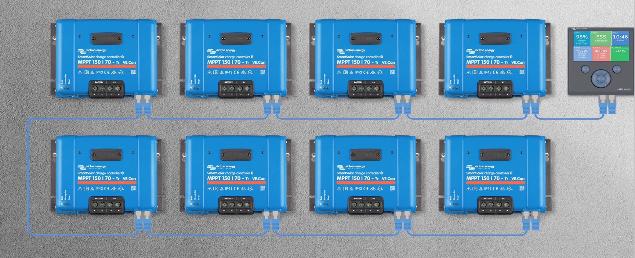
A terminator is only required at the start and the end of the bus.

Terminator-> Color GX CAN port 1

Color GX CAN port 2 -> Can device A port 1

Can device A port 2 -> Can device B port 1

Can device B port 2 -> Terminator

alt text


2 |3000

Up to 8 attachments (including images) can be used with a maximum of 190.8 MiB each and 286.6 MiB total.

masterredwind avatar image
masterredwind answered ·

Hi Guy,

Many thanks for your reply.

Unfortunately in my case I have another CAN device (a bms) already plugged into Color GX CAN port 1, so it won't be free to use for the terminator for my 150/70 mppt chain (connected to Color GX CAN port 2).

7 comments
2 |3000

Up to 8 attachments (including images) can be used with a maximum of 190.8 MiB each and 286.6 MiB total.

wkirby avatar image wkirby ♦♦ commented ·

There is only one CAN interface on the CCGX.
There are two connectors presented for this single interface to facilitate either a terminator or loop through. In other words the two connectors form an inbuilt "Y" for the CAN interface.

0 Likes 0 ·
masterredwind avatar image masterredwind wkirby ♦♦ commented ·

Thanks for clearing that up.

0 Likes 0 ·

Unless you are using identically spec'ed CANBus devices (eg VE.Can 250 kbit/s), then you will not be able to do what you are asking with the CCGX. It only has a single CANbus interface, and just adding additional ports with splitters will not work.

The Venus GX has two seperate CANbus interfaces, so it is possible to simultaneously connect a CAN BMS (eg 500 kbit/s) and a VE.Can (eg 250 kbit/s Victron MPPT).

There is only one battery that I can think of that uses VE.Can that would allow MPPT's and battery BMS on the same CANbus, that is the MG Energy Systems.

Other CAN BMS systems typically do not use VE.Can, this limitation is further described in the Victron BYD manual here.

0 Likes 0 ·
masterredwind avatar image masterredwind Guy Stewart (Victron Community Manager) ♦♦ commented ·

Thanks Guy, I had looked at the Venus as an alternative but didn't realise at the time it had two interfaces. That section of the BYD manual is a gold mine of information!

I'm assuming that there is no need to use terminators with the Venus, is that correct?

0 Likes 0 ·
masterredwind avatar image masterredwind masterredwind commented ·

You can ignore that question about the termintors, I can see they are still required for the Venus.

0 Likes 0 ·
wkirby avatar image wkirby ♦♦ masterredwind commented ·

CANBus cabling generally needs to have a terminator at each end of the cable. It cannot be assumed that any device will be at the end of the cable, so the system designer can decide the end and provide terminators where needed.
If the terminating resistors were built in to the device then that device could only be installed at the end of the cable.

The Venus GX has one of its CANBus interfaces presented as two RJ45 connectors, just like the CCGX. This is known as VE.Can and it is isolated.
The other interface is presented on a three way terminal block - CAN-H, CAN-L and GND. A 120Ω terminating resistor will be needed here if that will be the end of the cable.
Also to remember, unlike the VE.Can interface, this second interface is not isolated.

0 Likes 0 ·
masterredwind avatar image masterredwind wkirby ♦♦ commented ·

Thanks for the continued help.

I'll need to split out the CanH, CanL and GND wires into separate plugs to connect them to the Venus as the bms is wired up with an rj45 socket (see image below).

Also, the bms rj45 socket has two 12V pins (presumably for CAN power). Is this going to be an issue?

0 Likes 0 ·
bmscanconnector.png (128.0 KiB)

Related Resources

CCGX Product Manual

CCGX Product page

Additional resources still need to be added for this topic