question

valden avatar image
valden asked

Smart Lithium Battery manual - error in Appendix?

The attached screen shot is from the 2024 version of the Smart Lithium Battery manual. It's from chapter 8 - Appendix, 8.1 - Initial Charge Procedures Without BMS. The voltages in the columns for Absorption and Float look like they're the wrong way around to me. Or am I wrong about this? Thanks.
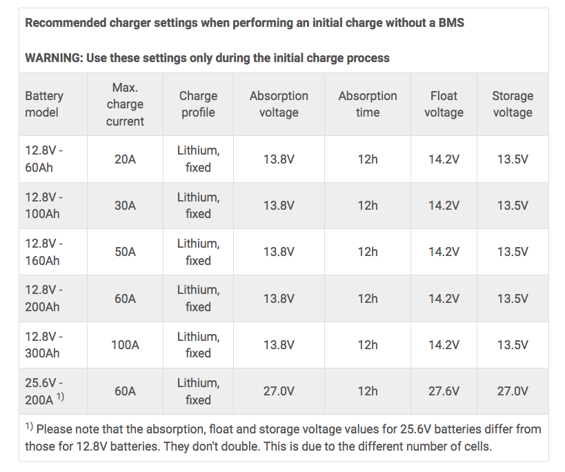
screen-shot-2024-05-26-at-174443.png

battery chargingsmart lithiummanual error
2 |3000

Up to 8 attachments (including images) can be used with a maximum of 190.8 MiB each and 286.6 MiB total.

2 Answers
pwfarnell avatar image
pwfarnell answered ·

I raised this very point with Victron some time ago and they confirmed after checking with tech people that the manual is correct and this came from high up in Victron, direct answer not through dealers.

2 comments
2 |3000

Up to 8 attachments (including images) can be used with a maximum of 190.8 MiB each and 286.6 MiB total.

valden avatar image valden commented ·

Thanks for chiming in with this history pw. Was your discussion on this topic captured in a thread in this community? Link? It’s likely that I won’t be the last Victron user to be confused by the table in 8.1. I did a search before asking this question of course.

Thanks. :-)

p.s. I have a suggestion for the Victron team members who edit this particular manual. Add a note to the table that explains that ‘This seemingly low absorption voltage is correct for this procedure.’

0 Likes 0 ·
Show more comments
klim8skeptic avatar image
klim8skeptic answered ·

@Valden Pretty sure the 13.8v chosen for the absorp voltage @ 12h is to prevent cell voltage runaway. At a cell voltage of 3.45v they will be better than 99% Soc after 12 hours.

From the manual. Cell voltages can rise very quickly as they approach full charge, so the person supervising may need to intervene immediately to prevent a dangerous cell over-voltage scenario

After 12h of absorp, there will be little balancing to occur during the 14.2v float charge period.

2 comments
2 |3000

Up to 8 attachments (including images) can be used with a maximum of 190.8 MiB each and 286.6 MiB total.

valden avatar image valden commented ·

Hi Klim.

Hmmm, I'll say I'm not entirely convinced but your proposal has me got me thinking. Let me paste in two of the dot points from 8.1.

  • The supervisor interrupts the battery charge process immediately should a battery cell voltage exceed 4 Volt.
  • The process is complete when all cell voltages are between 3.5V and 3.6V.

Taken together, these dot points describe the expectation that the cells will absorb charge unevenly. 13.8V is sufficient to lift a cell to 4V, but it is not enough the lift four cells to 3.5V simultaneously. Redistribution from cells that have reached voltages above 3.5V (as much as 4V) to lower cells would be needed to bring the four cells up to 3.5 or 3.6V, being the end point for the process. 13.8V could be the correct absorption voltage if cell balancing of this nature is a part of how it works.

So, you might be right about this. I'd like to hear from a Victron staff member who knows for sure. A fellow sailor is dealing with out-of-balance batteries as we speak and the chart in 8.1 doesn't look sensible to our eyes, at first viewing. :-|

I'll leave the question 'unanswered' in the hope that a subject matter expert can tell us what we need to know.

Thanks. :-)

0 Likes 0 ·
valden avatar image valden commented ·
But there's more.

I see in chapter 6.1.2, under Charge procedure for recovery after low voltage event, the first dot point says:

  • Set a charger or power supply to 13.8V

A BMS is used and will cut charging intermittently when a cell requires this.

So this is interesting and supports the view that the 13.8V absorption voltage in the chart in chapter 8, para 8.1 could actually be correct. :-)

Does anyone know for sure?


0 Likes 0 ·

Related Resources

Additional resources still need to be added for this topic

VictronConnect VE.Bus charging manual