question

gerdverreycken avatar image
gerdverreycken asked

Can an MPPT handle solar panel relay switching?

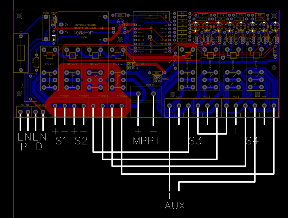
1715177951882.png

I have designed a relay board to switch my panels in 4 different configurations depending on load's weather etc. I have 4 strings of 3 series 440Wp panels. I have a Victron mppt / invertor on a DC battery system and also have an on-grid pv inverter. I designed the board so I can switch the panels in 4 routings. The board has a built in voltage meter for keeping the switching safe for the 150V MPPT. The 4 modes are:

1.) MPPT 1x6 + GRID 1x6 panels for dark conditions

2.) MPPT 2x3 + GRID 1x6 panels for brighter conditions

3.) MPPT 2x6 + GRID 0 panels for dark conditions with higher loads on the DC coupled side.

4.) MPPT 4x3 + GRID 0 panels for bright conditions with very high loads on the DC coupled side.

I am planning to do the switching in a cascade sequence programmed in Node-red.

So the mppt's invertor are first turned off remotely and the relais can switch under zero load.

I was wonder if you know this would give any problems?

Kind regards,

Gerd


MPPT Controllers
1715177951882.png (206.9 KiB)
3 comments
2 |3000

Up to 8 attachments (including images) can be used with a maximum of 190.8 MiB each and 286.6 MiB total.

phoenix avatar image phoenix commented ·

I also believe you are ok using relays to switch DC off load. It's no different to a connector. The voltage range is well below that of the DC equivalent of mains 230 * 1.414 = 325VDC.

You don't mention how you will disconnect the GTI. Relay on the mains side? There are some electronics in the GTI which pull power from the panels, but this is in the mA range and should be ok on say 16A relay contacts.

Is 6 panels on the mppt below the 150V limit. I have seen cloud go to sun in a split second- far faster than you can use NR to switch.

Your PCB has many problems. For example, the opto mains side bridges the 5V. Flip it and move it to under the trafo and mount it on the underside. Clearances between mains and PV, DC and PV are way too small, even with conformal coating. Etc, etc

I also doubt your 3W 5V supply can operate the coils on 8x16A 5V relays.

You'll get better feedback on an electronics forum.

0 Likes 0 ·
gerdverreycken avatar image gerdverreycken phoenix commented ·
The GTI has a remote input that accepts 4 signals for 0/30/60/100% output power. I have the needed interfacing to control that one so also those can be switched with near zero load.

The MMPT is the 150/100 and yes panel voltages can vary fast with sun breaking trough. dark clouds I realize that. But I am planning to leave a lot of headroom and only switch to 1x6 / 2x6 when the sun's azimuth and so on are safe. I will be very carefull with the conditions and will log things for a year at least and follow up before making the descision to activate the function.

I have built a similar relais boards and 4 of them are running for more than 4 years without any issues in my DIY home automation system. On those boards the spacing is indeed better and i have a double sided PE connected trace in between the 5/3.3V side of things and the AC as a safety line. I still have to do what you suggest, this is only a first attempt to order components and make the routing.

The isolated supply has no problems powering all coils + esp.

Thanks for your advise.


0 Likes 0 ·
Show more comments
3 Answers
Alex Pescaru avatar image
Alex Pescaru answered ·

Hi @GerdVerreycken

I am glad that you proposed such project and my response is more of making the community aware of the fact the DC switching is very different than the AC switching. One must make sure, as you've said, that there is zero load when switching.

Otherwise you must use special relays or contactors for that, as switching killowats of DC is quite difficult and must be done quickly, because if you don't, you'll end up in no time with fused or burnt contacts because the electrical arc is not extinguishing so easy in DC case.

For anyone interested, take a look at this video: https://www.youtube.com/watch?v=Zez2r1RPpWY

Thanks and sorry for hijacking the topic with this...

Alex


1 comment
2 |3000

Up to 8 attachments (including images) can be used with a maximum of 190.8 MiB each and 286.6 MiB total.

gerdverreycken avatar image gerdverreycken commented ·
You are absolutely right about the longer arc duration due to the absence of a trough zero current every 10mS. But thanks for the warning anyway.
0 Likes 0 ·
Michelle Konzack avatar image
Michelle Konzack answered ·

How do you handle this:


1.) MPPT 1x6 + GRID 1x6 panels for dark conditions

3.) MPPT 2x6 + GRID 0 panels for dark conditions with higher loads on the DC coupled side.


if you have only a MPPT 150?

I hope it is a 100A Model and your Batteries are 48V.


I do not know a single solarpanel above 200Wp which has lesser then 32Vmpp and 42Voc.


You can not have more then 3 panels in series.


Oh I should mention, Switches and Relais which are made for 230V AC, can handle 32V DC with the same current.


With 60V, the current is lesser then the half.


Now you want to handle 150/300V Solarpanels with a string current of minimal 10A?

The Print-Relais you want to use, are 100 times to small.


You need for your project Relais with Nitogen enclosed HIGH VOLTAGE contacts.

A relais which can switch 400V wit 16A const only (roughly) 600€.


Note: I had a similar Idea, but when my DISTRIBUTOR (NOT RESELLER) told me my price I had to sit down and got a hickup, because my project needed 6 of them.


I dropped the idea/project.

1 comment
2 |3000

Up to 8 attachments (including images) can be used with a maximum of 190.8 MiB each and 286.6 MiB total.

gerdverreycken avatar image gerdverreycken commented ·
150/100 indeed. 99% of the time i will indeed have only 3 panels in series.

6 panels only on the darkest days in winter just to give it a try. It is a matter of experimenting. Not at all something i am sure of it will work. Also I will leave enough headroom in the switching conditions to leave in a safety margin. I see no problems of switching DC on zero load with 16A print relais. So I will give it a try before dropping the idea.

0 Likes 0 ·
klim8skeptic avatar image
klim8skeptic answered ·

@GerdVerreycken You know that the mppt's in both your grid tie inverter, and the Victron DC mppt's already search for the pv array maximum power output with varying solar insolation input?

Panel Imp is almost directly proportional to solar insolation.

Panel Vmp only drops a little with diminishing solar insolation.

I fail to see what improvement could be achieved with your idea.

1 comment
2 |3000

Up to 8 attachments (including images) can be used with a maximum of 190.8 MiB each and 286.6 MiB total.

gerdverreycken avatar image gerdverreycken commented ·
I see your point, and yes in 99% of the time i will just run 3 panels. The 1% is me experimenting with my panels on very very dark winter conditions to see if I can improve things a bit. I needed a board to switch my panels between grid/offgrid invertor anyway so i included 4 extra relais to fool around a bit with series/parrallel switching.
0 Likes 0 ·