question

ee21 avatar image
ee21 asked

Multiplus efficiency far lower than expected? Is something wrong?

I have tried to test the efficiency of my inverter/charger, but what I am finding is that at best it is around 89% efficient, which according to spec should be up to around 94%. I am hoping someone can help clarify, or correct my findings, any input is appreciated...


My test setup, is using the MultiPlus Compact 24/2000. I have tested using the built-in battery monitor, as well as a BMV-712, both monitors show identical values.


I run the inverter with a set limit of 500W, which is a little less than 1/3 the maximum continuous output at 25* C. The BMV and MultiPlus both show an average discharge of 565W. Unless I am doing my math incorrectly, that means about 11% of the energy being drawn from the battery pack is being lost as heat by the MultiPlus. Again, unless I am mistaken, this would mean the efficient of the inverter would be considered as 89% efficient. This is the best value I can get. If I raise the inverter power the efficiency only goes down further.


Looking at this chart found here on page 3: https://www.victronenergy.com/upload/documents/Output-rating-operating-temperature-and-efficiency.pdf

The MultiPlus 24/3000 has an optimal efficiency when run at between 400W and 800W. 400W being 1/6 of 2400W, and 800W being 1/3 of 2400W.... I am running right in between this for my test, at 500W out of 1600W rated. Ambient temperature is around 22*C, and I never see the temperature sensor in my inverter hit 30*C.


Can anyone provide any insight as to why I am not seeing efficiencies at, or over 90% ever, at all? 65W of heat isn't that much from one unit at low load, but I have a 1x2 Split-Phase setup at the moment, with 3.2KWP, and and am looking at doubling that to 2x2 parallel/split-phase. I was really hoping to see a bit better efficiency with these inverters over my old AIMS one.

MultiPlus Quattro Inverter Charger
3 comments
2 |3000

Up to 8 attachments (including images) can be used with a maximum of 190.8 MiB each and 286.6 MiB total.

gnagflow avatar image gnagflow commented ·

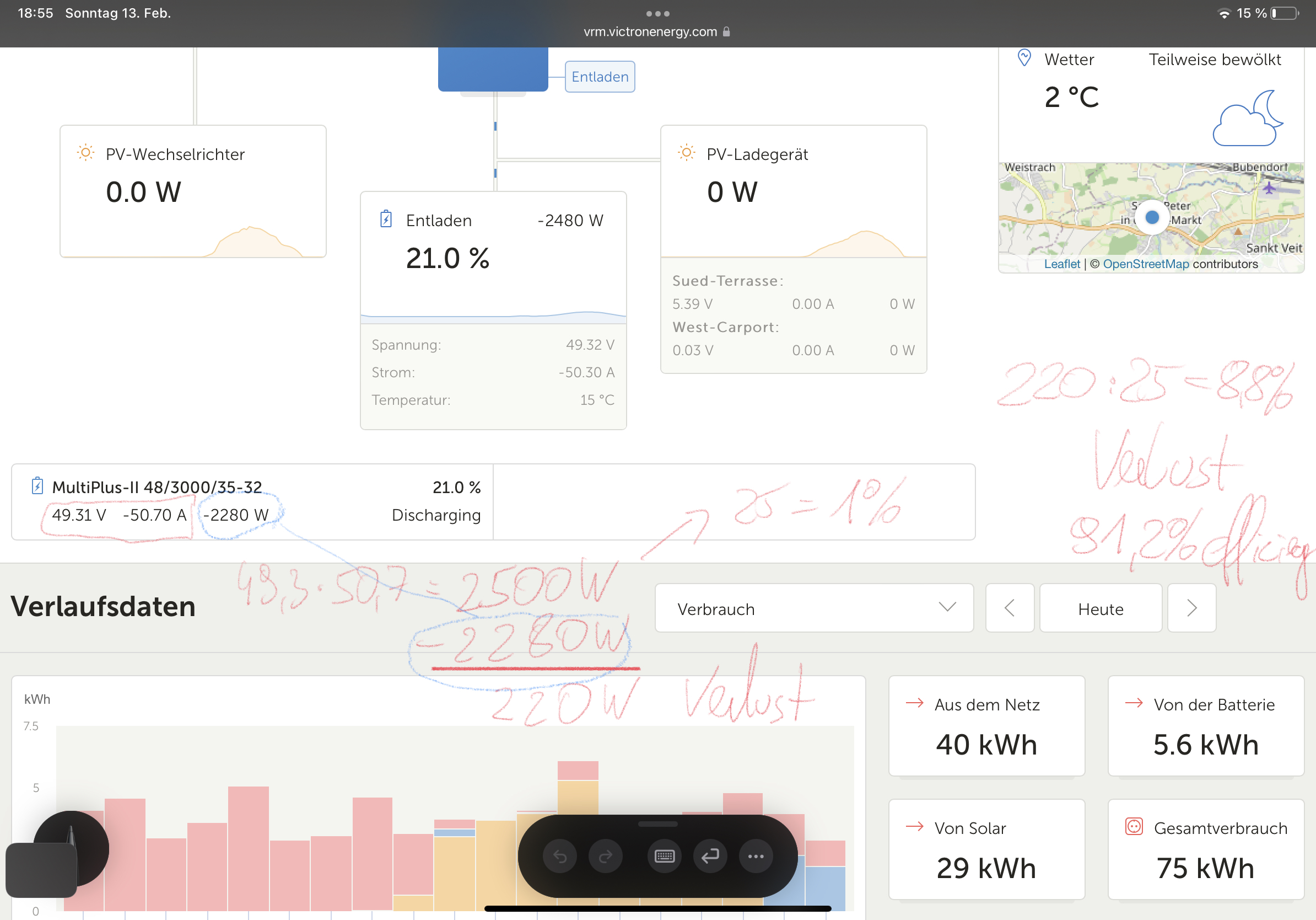
Unfortunately i have a very similar problem. I have grid settings with cos phi = 1, which means my inverter does not produce any reactive power.

I switched my 3 multiplus2 (3kVA) to max. 800W each because this is according to the efficiency graphs the most efficient output power —> 3x 800W =2.3kW

I can do and measure what i want, but the best for DC->AC is about 91.5% efficiency with 800W output power. If i do more output power the efficiency is much lower. Unfortunately this is very dissatisfying.

Look at the picture, you see below the DC measurements from the Multiplus and the AC measurements from the MP2. Data is coming from the inbuilt measurements of the MP2. If i check the data, the BMS gives almost the same DC current and voltage, the AC output is conform to the grid meter. So data should be right.

The temp is about 16 degree.

There is no way to get the efficiency like the data sheet shows.

I measure this since a year, i am not able to get the inverter heat lost below 10%.

The round trip efficiency is 81% at my system, but DC is coming maybe 85% from MPPT’s without any additional lost.

0307816b-16fb-4432-8d5d-cb411062e6a0.jpeg

0 Likes 0 ·
gnagflow avatar image gnagflow commented ·

I use the MP2 3000/48/30-32

I see it exactly as you see it, did you get any answer why the inverter is never as efficient as in the datasheet says, where you provided the link!

All the answers below say that your measurement is incorrect or your reactive power is too high.

My fixed cos phi = 1, no reactive power with my grid code. Measured 100 times and the values are confirmed. The multiplus DC values are confirmed by the shunt measurements of the BMS, and the MP2 AC values are confirmed by the grid meter.

The question is, if anyone on the world can confirm the values on the data sheet? There is never an efficiency of 95% in the best setup (Pulling 500-800W and low temp.) The efficiency is about 90-93% at this working point, which is far away of >94% according the datasheet.


0 Likes 0 ·
ben avatar image ben ♦ gnagflow commented ·
Well, technically, the datasheet says "maximum." And it's just theoretical, I suppose.


My inverters never don't ever achieve the maximum, either, although they come about as close as your measurements.

Without a tighter spec, it's hard to really say what's what. But I suspect your inverters are performing similarly to others'.

0 Likes 0 ·
4 Answers
Mark avatar image
Mark answered ·

I am no expert on the topic, but it could be that the power factor of the load that your running is <100% - meaning that the voltage and current sine wave is not in perfect sync.

As such peak voltage and peak current will not be aligned and power reported in W (on the inverter AC side) will be lower.

If you purchase even a cheap plug in AC energy meter it should be good enough to display the power factor, the power in W, the current in A & the voltage in V.

When the power factor is perfect/100% then VxA will be equal to the power reported in W. But when the power factor is lower, then VxA will be GREATER than the power reported in W (on the inverter AC side).

1 comment
2 |3000

Up to 8 attachments (including images) can be used with a maximum of 190.8 MiB each and 286.6 MiB total.

ee21 avatar image ee21 commented ·

I did not realize the Watt reading of the BMV would be incorrect in this case. I do have some computer and networking equipment on the AC Out side.

0 Likes 0 ·
ben avatar image
ben answered ·

To know for sure, you'll need to put a meter on the AC output and measure it. The metering in the Victron inverters is not always super accurate in my experience.

1 comment
2 |3000

Up to 8 attachments (including images) can be used with a maximum of 190.8 MiB each and 286.6 MiB total.

ee21 avatar image ee21 commented ·

Thank you for the advice, I had been simply relying on the AC Out reading of the MultiPlus.

0 Likes 0 ·
Matthias Lange - DE avatar image
Matthias Lange - DE answered ·

What do you use to produce the load? Are you sure it is exactly 500W?

2 comments
2 |3000

Up to 8 attachments (including images) can be used with a maximum of 190.8 MiB each and 286.6 MiB total.

ee21 avatar image ee21 commented ·

There is a variety of household equipment connected to the AC Out, including computer equipment. The load is over 1000W, but the test was done by setting the Maximum Inverter Power limit in ESS.

0 Likes 0 ·
Matthias Lange - DE avatar image Matthias Lange - DE ♦ ee21 commented ·

You can't say that your Multi has a bad efficiency by making such a clumsy "test".

The efficiency mentioned in the manual are only for resistive loads. You have mixed loads(resistive, capacitive and inductive) , that lowers the efficiency.

If you want to measure the efficiency correctly, you have to use resistive load with defined value, measure AC output V and A (V*A=W <- should be the value of the defined load) and measure DC input V and A (V*A=W <- a bit more then output).

Difference between output and input -> efficiency

1 Like 1 ·
klim8skeptic avatar image
klim8skeptic answered ·

Battery voltage probably has some efficiency input.

1 comment
2 |3000

Up to 8 attachments (including images) can be used with a maximum of 190.8 MiB each and 286.6 MiB total.

ee21 avatar image ee21 commented ·

I was wondering about this, I am using 7S NMC battery modules, which have a range of 28.6V down to 21.4V cutoff. Since this is the upper range of the inverter's voltage range, I would hope the higher voltage would translate to slightly higher efficiency, but I do not know.

0 Likes 0 ·