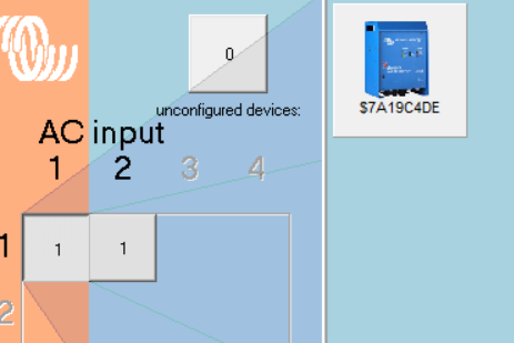
i connected 2x multiplus II to some battery's and wanted to use these like a quattro.
but when i connect 1 of the multi's to the ac inputs, the inverter goes in overload
This site is now in read-only archive mode. Please move all discussion, and create a new account at the new Victron Community site.
i connected 2x multiplus II to some battery's and wanted to use these like a quattro.
but when i connect 1 of the multi's to the ac inputs, the inverter goes in overload
Can you make a schematic or some pictures of your setup?
Make sure that you didn't mixed up AC IN and AC OUT.
I checked the connections 3 times. It starts charging for 1 second and switches off. If I disconnect the ve bus and than start charging it works
i thought this was right
2 inverters in 2 different ac inputs (1 inverter- 1 input)

When Multis/Quattros are connected in parallel, ALL inputs and outputs must be paralleled with equal length cables. The master unit controls both it and all slaves: invert/charge mode and the amount of power to pass through the inverter/charger core. The result is nearly identical power flow in both master and slave.
If the master has an AC source, then it will set both units to charger mode but the slave has no AC input and will fail. If the master has no AC source, then it will set both units to invert but the slave unit has an AC input which might not be ignored. This too would cause a failure.
What you need to do is wire both units in parallel (all ins and outs), then install a transfer switch ahead of the AC input of the pair of Multis. The external transfer switch can then choose the desired AC input source.
There is no way to use separate AC sources simultaneously.
Yeah I get that. What I really want to do is 1 multi a dedicated charger and the other only inverter. But connected with 1 vebus to a Ekrano, so the battery can limit the charging and discharge current through dvcc.
But, there is no logic to recognize one Multi as charger and one as inverter. One will be chosen as "THE" Multi displayed on the GUI and used for system calculations while the other won't be shown on the flow page at all. I don't know if the "other" unit will be involved any DVCC calculations. I also don't think there is a way to choose which Multi is chosen as "THE" Multi.
It may be that connecting one unit via the dedicated VE.Bus connection on Ekrano and the other via a VE.Bus to USB dongle might be necessary and might provide a choice of "THE" Multi. But I'm guessing.
149 People are following this question.