question

victronication avatar image
victronication asked

Color Control doesn't see 5th Pylontech battery! Help pls! :)

Background: Hi folks. I have a small off-grid set up based around the Victron Multiplus 48/3000. Up until recently the battery array was 4 x Pylontech US2000s. Last week my electrician added a Pylontech US5000 to the set up as the new master battery, to add additional capacity, bringing the total of batteries to 5.

The problem: as per the Color Control screenshot below, the Victron will only see 4 batteries, NOT 5.

screenshot-2024-04-18-at-72355pm.png

I have asked the off grid system supplier and my electrician and no one seems to know why this is the case. Help me Obi Wan Kenobi, you're my only hope! Thanks so much in advance.

--------

Additional background:

New Pylontech US5000 set up as master battery
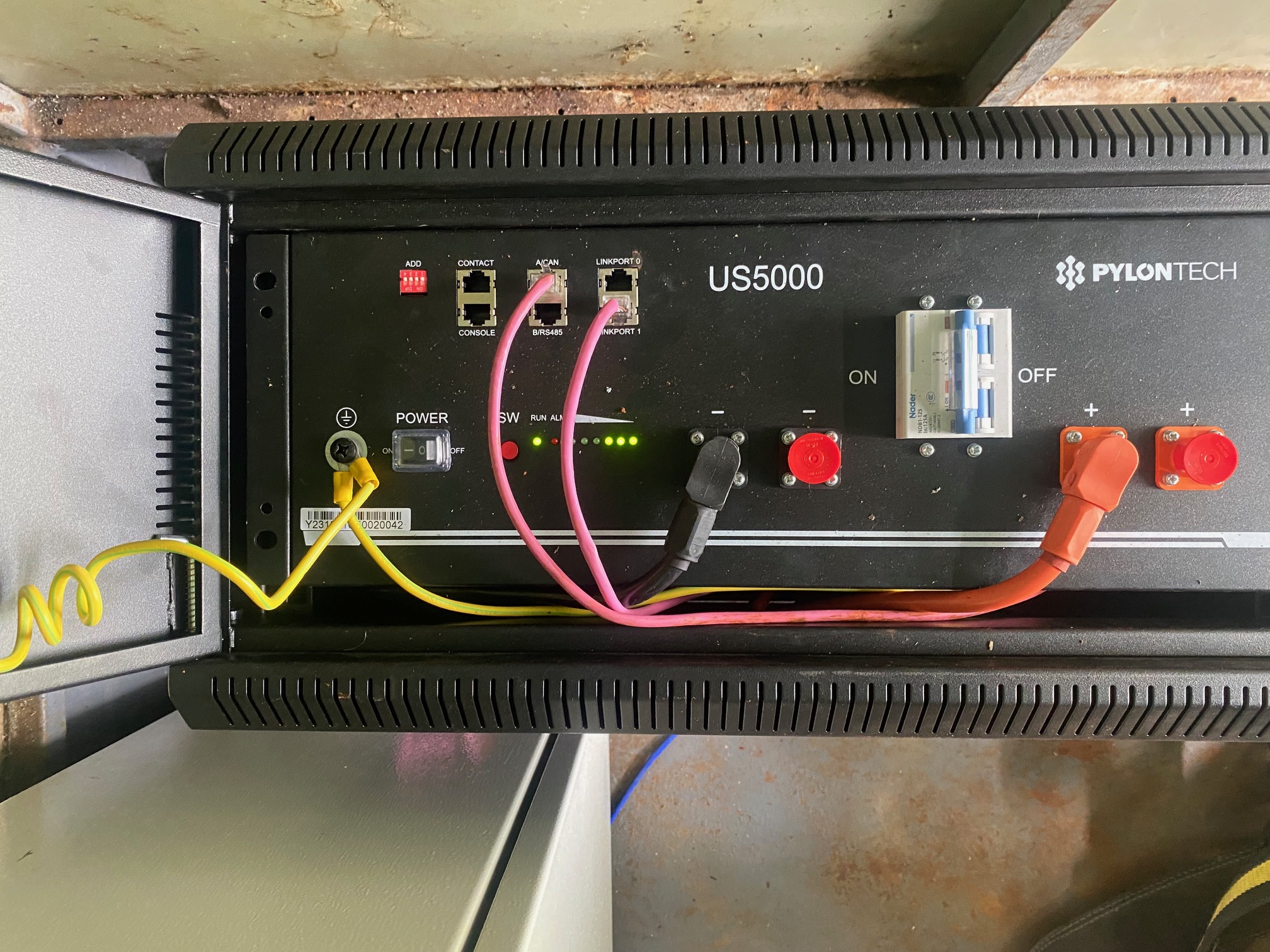
img-2859.jpg
4 x Pylontech US2000s as slave batteries
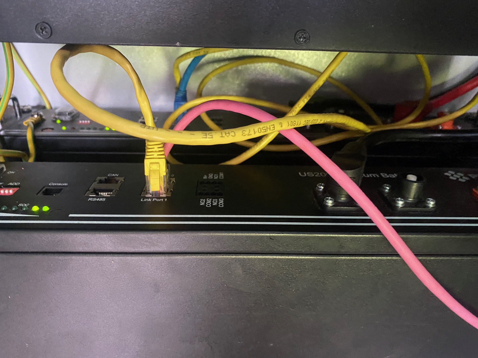
img-2860.jpg

img-2861.jpg

The board including a Sunnyboy PV inverter, and the Multiplus:
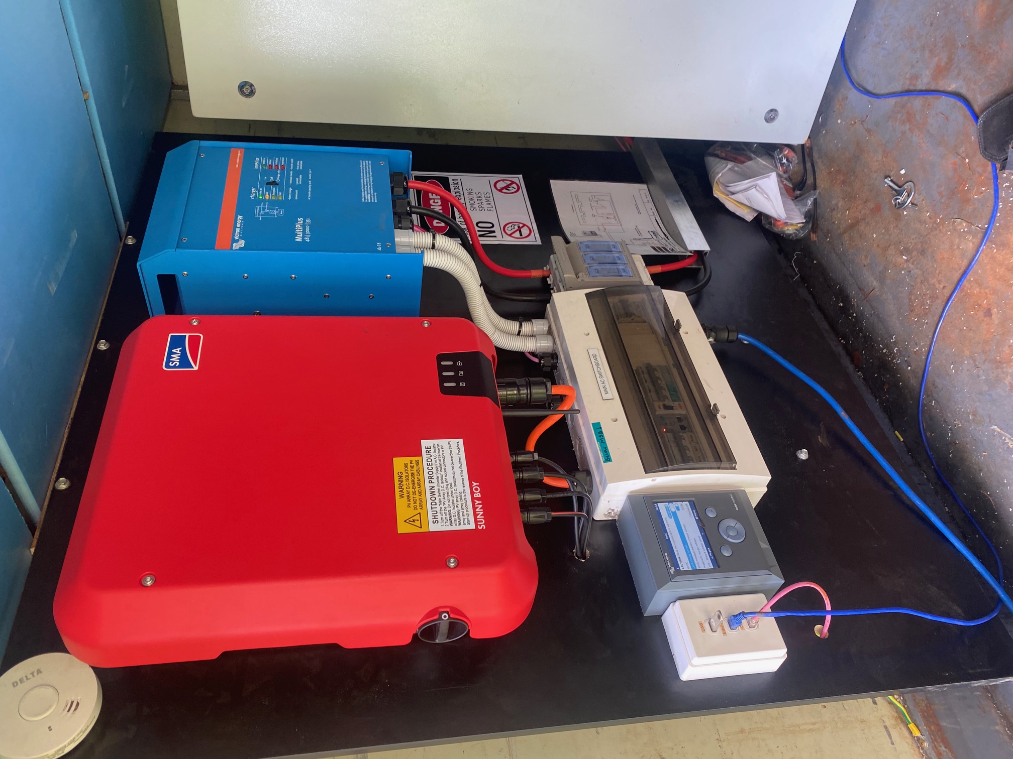
img-2862.jpg


Multiplus-IICCGX Color ControlVictronConnectPylontechbattery
img-2859.jpg (895.2 KiB)
img-2860.jpg (734.8 KiB)
img-2861.jpg (716.3 KiB)
img-2862.jpg (581.4 KiB)
7 comments
2 |3000

Up to 8 attachments (including images) can be used with a maximum of 190.8 MiB each and 286.6 MiB total.

Alexandra avatar image Alexandra ♦ commented ·

@Victronication

Did you set any of the dips?

Also the comms cable. Did you just use the original one you had from the bank? They are different between 5000 and 2000.

(Might need to remove pin 3. Gnd.)

You can test and see if it picks up just the 5000 by itself.

1 Like 1 ·
victronication avatar image victronication Alexandra ♦ commented ·

What configuration should they be in in your option?

0 Likes 0 ·
victronication avatar image victronication victronication commented ·

I ask because they are in CAN configuration and I was told by the supplier that dips should be switched to 'off'. So no, I haven't touched the dips. Comms cable is not the original one from the bank. The electrician made up a new one from scratch.

0 Likes 0 ·
Alexandra avatar image Alexandra ♦ victronication commented ·

Just checking. Sometimes the dips get bumped.

Does the us5000 register by itself on the GX?

1 Like 1 ·
victronication avatar image victronication Alexandra ♦ commented ·

I am getting over 150 amps so between the 4 batteries that tells me that all 5 batteries are likely being registered by the system. However, no, the system only sees 4 batteries, and the likely culprit is the US5000.

0 Likes 0 ·
Duivert NL avatar image Duivert NL victronication commented ·
Did you changed the CAN bus cables already with ones that have the correct pinout?
0 Likes 0 ·
Alexandra avatar image Alexandra ♦ Duivert NL commented ·

Test with just the 5000. No other batteries. If it registers build from there.

US2000 discharge usually at 25A so 4 give 100A. Not sure how you would see 150A if only the us2000 registered.

0 Likes 0 ·
3 Answers
Duivert NL avatar image
Duivert NL answered ·

alexandra is right:

from the victron pylontech setup page:

Type A cable

The Victron VE.Can to CAN-bus BMS type A Cable, part number ASS030710018 is used for connection with US2000C / US3000C / UP5000 / US5000 / US5000B / Force-L.

Type B cable

The Victron VE.Can to CAN-bus BMS type B Cable, part number ASS030720018 is used for connection with US2000 / US3000 / UP2500;

Note you cannot use the comms cable supplied by Pylontech for this connection between the master battery and the GX device.


see:https://www.victronenergy.com/live/battery_compatibility:pylontech_phantom


and here is the pinout for the cables:

3.1 Type A

Function Victron VE.Can side Battery side
GND Pin 3 Pin 6
CAN-L Pin 8 Pin 5
CAN-H Pin 7 Pin 4

3.2 Type B

Function Victron VE.Can side Battery side
GND Pin 3 Pin 2
CAN-L Pin 8 Pin 5
CAN-H Pin 7 Pin 4


see:https://www.victronenergy.com/live/battery_compatibility:can-bus_bms-cable


so you will need a cross cable between the 5000 and the 2000's

2 |3000

Up to 8 attachments (including images) can be used with a maximum of 190.8 MiB each and 286.6 MiB total.

jkkm avatar image
jkkm answered ·

I would check the interlink cables i.e. pink/blue/yellow/white. If one is not showing up it would be related to that. I have heard this happen where a cable is faulty.

Check this link as well for the CAN cable pin outs if you want to make one up

VE.Can to CAN-bus BMS cables manual [Victron Energy]


2 |3000

Up to 8 attachments (including images) can be used with a maximum of 190.8 MiB each and 286.6 MiB total.

kevgermany avatar image
kevgermany answered ·

Looks like an interlink cable is missing a connection at one end. You have two empty top sockets, should only be the one on the US5000 empty.

@Alexandra please correct me if I'm wrong.

2 comments
2 |3000

Up to 8 attachments (including images) can be used with a maximum of 190.8 MiB each and 286.6 MiB total.

Duivert NL avatar image Duivert NL commented ·
the cabling sequence is correct from pink to yellow to bleu to white if you look close

5000 top is empty, last 2000 bottom is empty

1 Like 1 ·
kevgermany avatar image kevgermany ♦♦ Duivert NL commented ·
Thanks. The upside down pic threw me.
1 Like 1 ·