question

mworl avatar image
mworl asked

Multiplus2 240V with an Autotransformer on US Split Phase = No ESS?

I have a Multiplus 2 240v 5kva inverter that has been in use for years in a mobile application working fine. It is set up with an auto transformer on the output for split phase 120/240 in the vehicle.

Shore power is from the two hot legs of US split phase. 240v between them, neither bonded to ground. Grid neutral wire is not connected to the vehicle. I have a hardwired bond between Neutral and Ground in the load center immediately after the auto transformer. This is necessary because under no circumstances do I ever connect to ground bonded neutral. Ground relay disabled obviously.

That vehicle is now permanently stationary and hard wired to 240V grid power. So far the only change was the shore power plug replaced with hardwired grid input and has been working as normal which was great for a mobile set up but now I am behind an anti-islanding relay and want to export all my excess solar generation. 3kw of panels on the top.

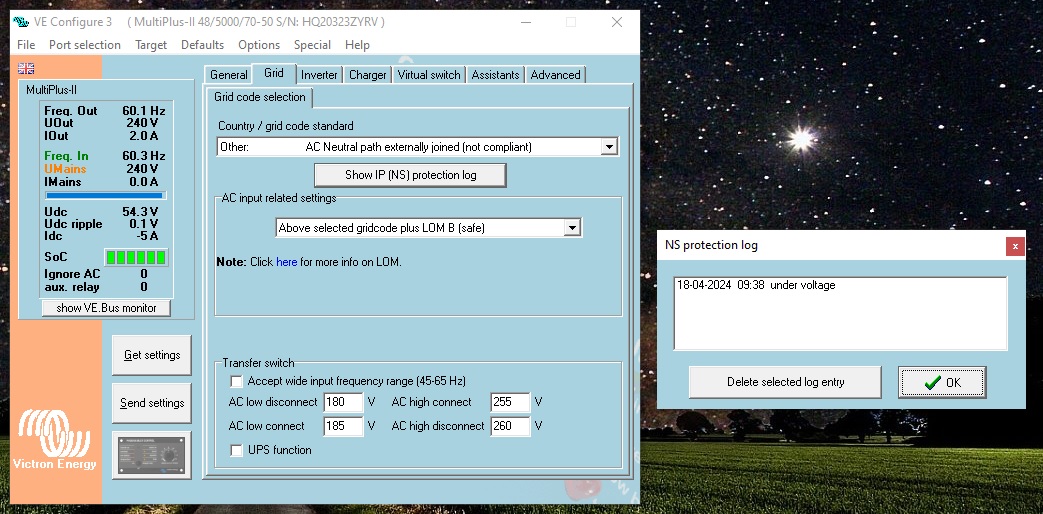
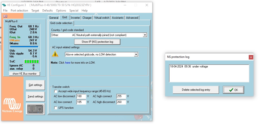
Today I updated the firmware, set the grid code to Other: Neutral Externally Joined, and added an ESS assistant. The inverter will not accept the AC input, reporting Under Voltage in the IP (NS) Protection Log. It retries periodically and makes a loud rapid clicking noise from inside the inverter, a relay I assume. In VE Config UMains is yellow despite showing the same voltage as UOut. Frequency is also well within range.

For testing I ungrounded the Multiplus and used the Other grid code which has the ground bond relay permanently enabled. Everything worked perfectly including grid export for a few minutes until the ground relay test failed error was tripped.

So, any ideas why the perfectly good grid power is being rejected? No momentary voltage drop and there is properly sized wiring all the way back to the service entrance, only about 150ft away. Could this have to do with there being no neutral bond on either of the incoming hot wires for some reason?lom-problem.jpg

Multiplus-IIESSgrid relay
lom-problem.jpg (188.6 KiB)
2 |3000

Up to 8 attachments (including images) can be used with a maximum of 190.8 MiB each and 286.6 MiB total.

3 Answers
rickc avatar image
rickc answered ·

Hypothesis (someone check my logic here):

Shore power has a N-G bond, presumably in the split-phase panel as is standard_

You‘ve hardwired a second N-G bond from the Autotransformer Neutral to the same shared ground.

The ground wire is likely carrying objectionable current from the vehicle back to the main panel, because both the grid neutral and the auto transformer neutral are effectively connected through the ground.

1 comment
2 |3000

Up to 8 attachments (including images) can be used with a maximum of 190.8 MiB each and 286.6 MiB total.

mworl avatar image mworl commented ·

I gave the trailer its own independent ground and the problem persisted. Thank you for the hypothesis though.

0 Likes 0 ·
Alexandra avatar image
Alexandra answered ·

@mworl

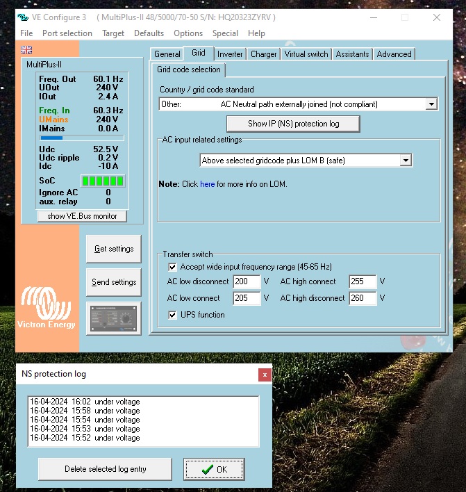
Not a mystery - remove the UPS function.

Ups function is not compatible with the ESS assistant because of the grid test method and frequency shift. (It actually auto removes the setting when you run the wizard)

You are giving conflicting parameters ups and wide frequency as well are not compatible. UPS very intolerant of change in grid (think of a computer UPS)

3 comments
2 |3000

Up to 8 attachments (including images) can be used with a maximum of 190.8 MiB each and 286.6 MiB total.

mworl avatar image mworl commented ·

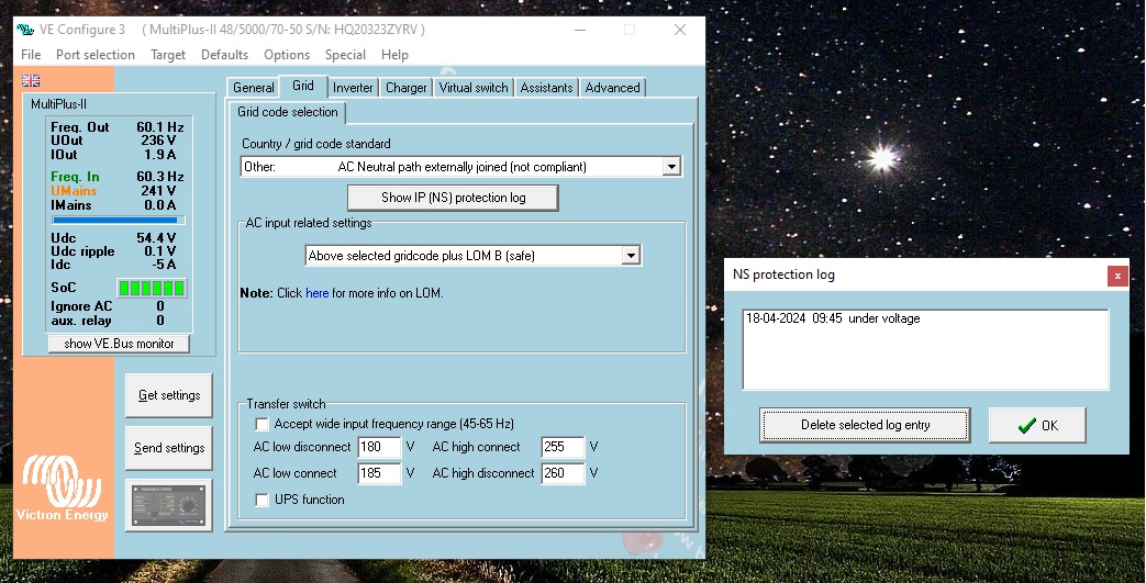
I removed the UPS and Wide Frequency settings and had no effect. Still refusing to connect to grid and reporting under voltage. I then set my inverter to 236V and still got an Under Voltage line in the protection log while the mains were at 241V.

I am starting to think that either there is either a hardware problem in my inverter or a firmware issue with the "Other: AC Neutral Path Externally Joined" grid code.


lom-problem2.jpg

lom-problem3.jpg

lom-problem4.jpg

0 Likes 0 ·
lom-problem2.jpg (194.2 KiB)
lom-problem3.jpg (129.8 KiB)
lom-problem4.jpg (213.0 KiB)
mworl avatar image mworl commented ·
@Alexandra


I have come up with a workaround detailed below in its own answer to my question. As you seem to be knowledgeable on this topic I would appreciate any input you have. Thank you for your time

0 Likes 0 ·
Show more comments
mworl avatar image
mworl answered ·

So I would like any input on the workaround I currently have set up. I connected the Multiplus to its own dedicated ground rod. About 150 feet from the primary ground rods at the property main panel. The trailer chassis and electrical system is still connected to the primary property ground. The neutral in the panel after the AT is bonded to that primary ground. This has resulted in the system operating as desired. The Multiplus is happy with it's internal NG bond relay closed.

I have taken readings of between 0.1 and 8v AC between the two grounds, though recently I have only seen below .5v ... The voltage differential between the case of the inverter (as well as the ground rod) and the chassis of the vehicle makes me nervous. Is there a potential for this voltage to reach hazardous levels?

I also read 120v and ~50 ohms between L1 at the inverter and either ground. This is confusing me. The inverter ground relay should be bonding L1 and the new Ground, so shouldn't they have no voltage between them?

Resistance between the two grounds is 2.2k ohms.


2 |3000

Up to 8 attachments (including images) can be used with a maximum of 190.8 MiB each and 286.6 MiB total.