question

andy-l avatar image
andy-l asked

Multiplus 2 ess showing load on AC Output 1 when it's not connected to anything

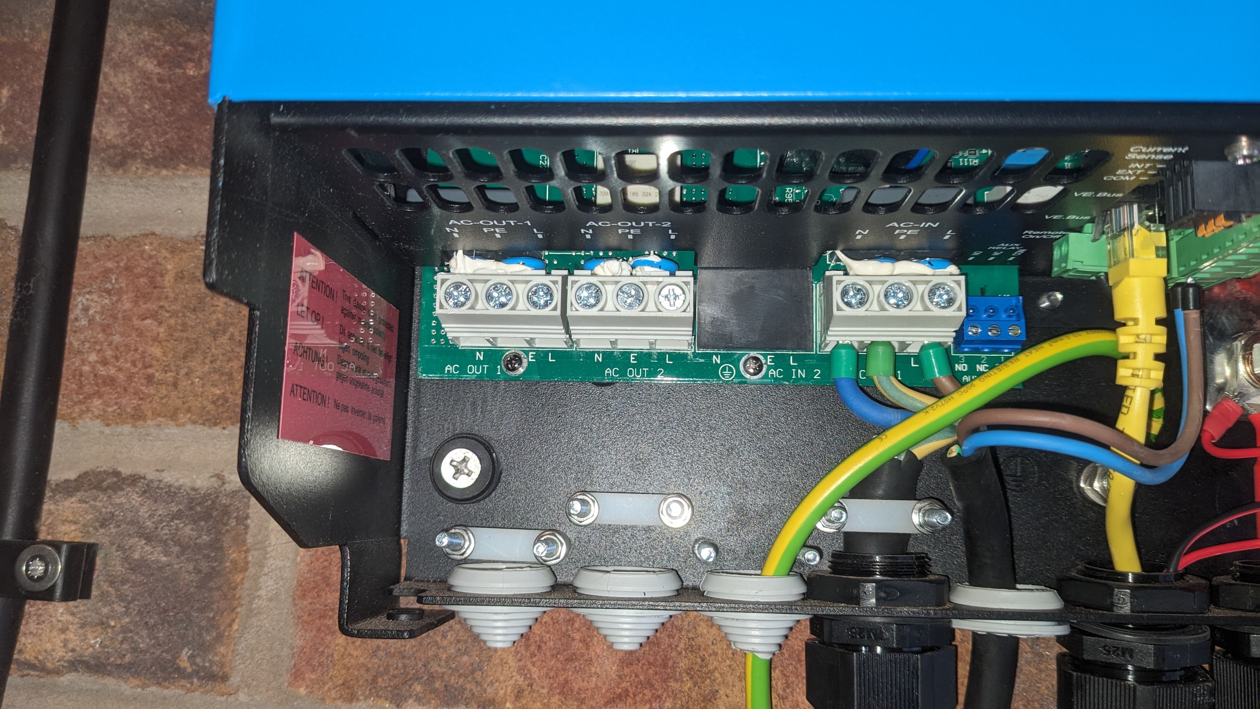
I have installed a ESS system using a multiplus 2. I have connected the inverter parallel to the grid via AC iput 1. I don't have any of the AC outputs connected.

I have a 4kw solar system on the same side as AC input 1. I measure the grid via a ET112 meter and the solar via a Victron AC Current Sensor on the temp sensor input of the mutliplus.

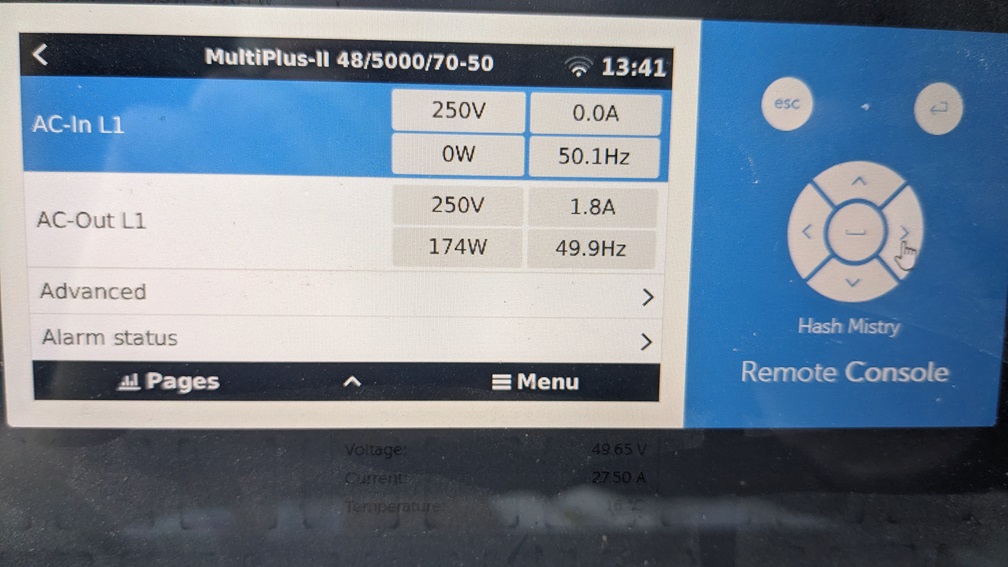
It's constantly showing a load on AC output 1 eventhough nothing is wired to it. The whole system shows power going to and from the grid which doesn't match what the solar is producing along with any out put from the batteries.
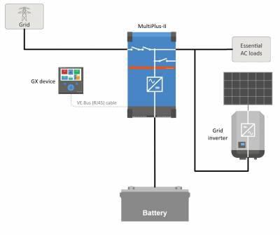
ess-system.jpgCan anyone point me in the right direction as to where the issue might be?

Multiplus-IIess dischargingac coupling
ess-system.jpg (10.2 KiB)
2 |3000

Up to 8 attachments (including images) can be used with a maximum of 190.8 MiB each and 286.6 MiB total.

1 Answer
Jason - UK avatar image
Jason - UK answered ·

@Andy L The reason for this is the latency between the ET112 & the MPII unit. The figues provided are a calculation between the grid meter (ET112), the PV meter and the inverter / charger of the MPII unit. Due to the latency of the ET112 because of the conversion from RS485 to USB to the internal BUS of the MPII unit, you get readings that don't always add up.

There is a data sheet stating the latency of all of the approved meters & sensors. The ET112 is one of the worst performing. I also have a ET112 with the same issue of odd reading.

6 comments
2 |3000

Up to 8 attachments (including images) can be used with a maximum of 190.8 MiB each and 286.6 MiB total.

andy-l avatar image andy-l commented ·

Hi Jason

I had originally used a CT clamp, but when that was fitted it wouldn't show the load on the house when the solar was running. So I installed the ET122.

The latency still doesn't explain why the AC out of the inverter is showing as a load when nothing is wired to it

pxl-20240403-171716667.jpg

pxl-20240411-124156549.jpg


0 Likes 0 ·
ejrossouw avatar image ejrossouw andy-l commented ·

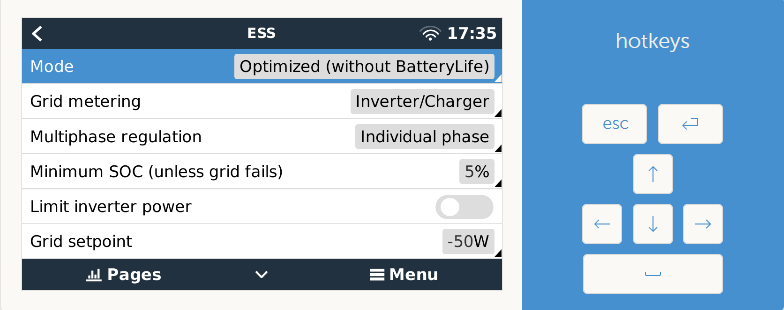
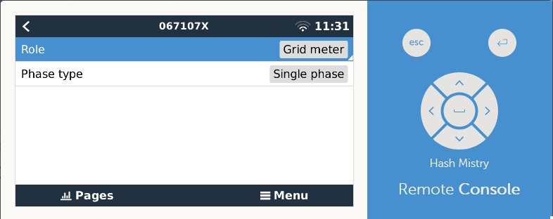
PS - The above diagram is not correct for your setup as it actually shows critical loads and an PV inverter on the ACOUT1 That aside, ensure that grid metering is set external meter. The below example is using a CT hence the Inverter/Charger setting. Also, ensure the role for the ET112 is grid meter.

1712853392639.png

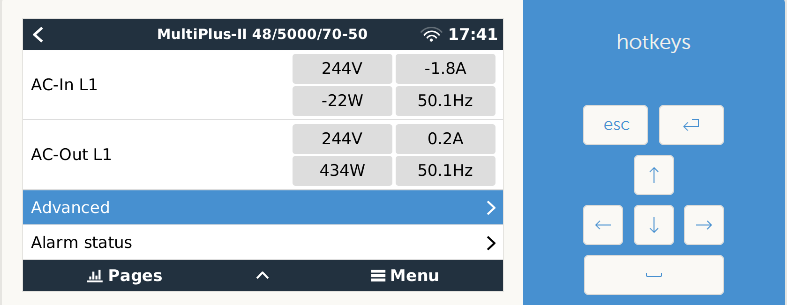
I would actually expect the following view if the system is set up and wired correctly.

1712853761052.png


0 Likes 0 ·
1712853392639.png (41.3 KiB)
1712853761052.png (34.5 KiB)
andy-l avatar image andy-l ejrossouw commented ·

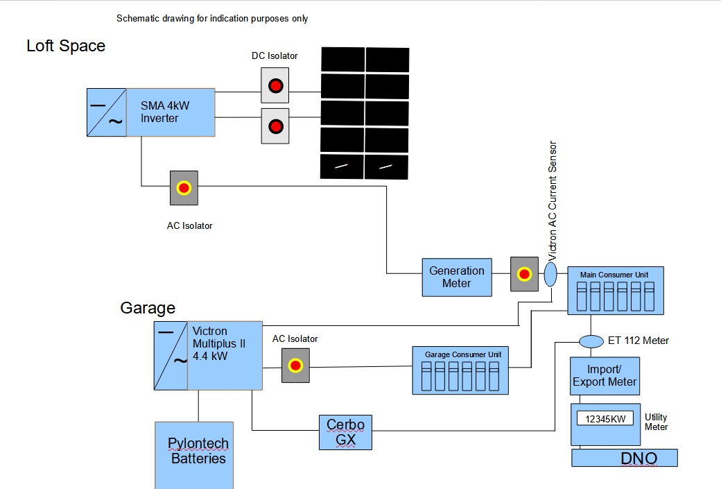
Here's a schematic of my setup

schematic.jpg


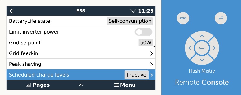
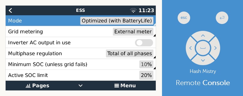
ESS settings

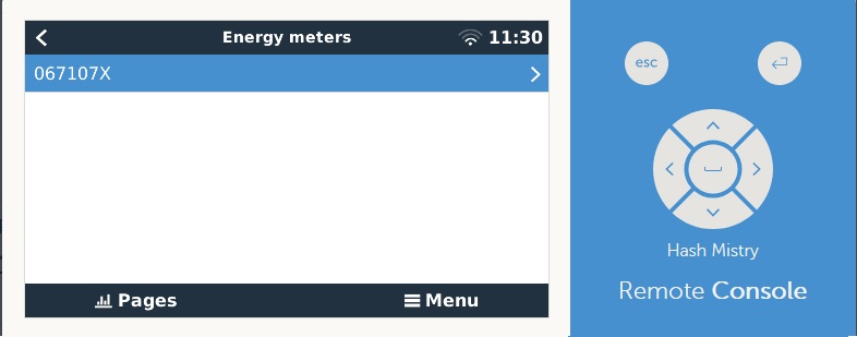
ess2.jpgess1.jpgenergymeter1.jpg

energymeter2.jpg


0 Likes 0 ·
schematic.jpg (98.8 KiB)
ess1.jpg (59.6 KiB)
ess2.jpg (53.1 KiB)
energymeter1.jpg (36.6 KiB)
energymeter2.jpg (42.9 KiB)
ejrossouw avatar image ejrossouw andy-l commented ·
Looks in order. Did you install the assistant for the AC sensor? Sounds silly, but is the ET112 installed correctly with grid coming in on the left to loads on right?
0 Likes 0 ·
Show more comments

Related Resources