question

littlewiggler avatar image
littlewiggler asked

Trying to understand voltage difference with 150/35 MPPT

System:

Color Control GX (2.33)

BMV-712 Smart (connected to GX via VE.Direct1) (4.01) Bluetooth network for MPPT Charger

MultiPlus Compact 12/2000/80-50 120V (connected to GX via ethernet) (430)

SmartSolar Charger MPPT 150/35 (connected to GX via VE.Direct2) (1.42 - updated on Wednesday from 1.39) Bluetooth network with BMV

3 Renogy 100 AH Lithium batteries in parallel

Was 4, now 5 Renogy 100 Watt Mono Panels (VOC: 21.6V, ISC 6.24A) 5th panel added today for testing. Wired in series.


BMV is autoselected as the Battery Monitor on the CCGX and


10 Gauge solar cables to SmartSolar MPPT 150/35 from the panels

6 (edit - originally said 4) Gauge wire between MPPT and batteries - 6.5 feet. Shutoff on positive and buss bar between them.

4/0 wire from batteries to MultiPlus 14' away. Uses same bus bar as the MPPT.


Salt Lake City, UT area if that matters.


Question/Issue:

I am measuring 101.1 Volts and 5.1 Amps on the wires coming from the solar panels. This was done with the wires removed from the MPPT and measuring at the point where they would be connected.


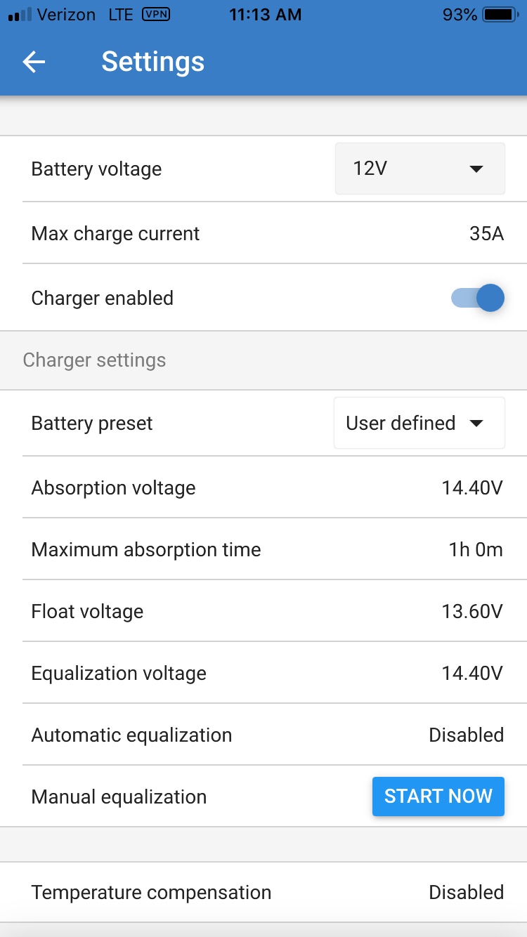
The MPPT controller is only showing about 1/2 the amps and only about 90% of the volts (see screen shots).


Why would there be that big of discrepancy?


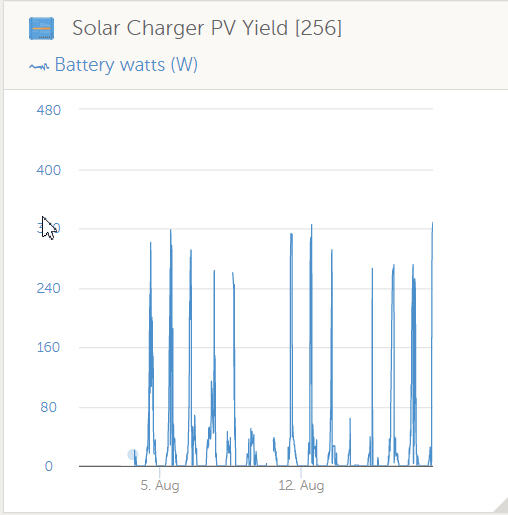
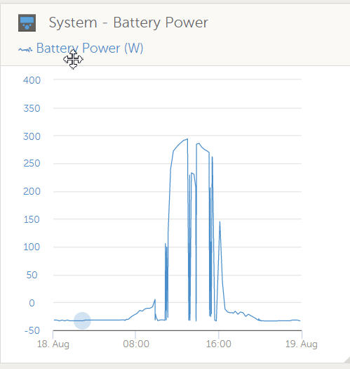
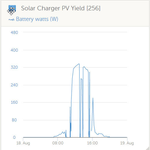
I have had this problem for a few weeks now. With 4 x 100 panels I was only getting a max of 320 Watts according to history - for the most part it was down in the low 200's. This is with 90-100F outside temps in full sunlight around 1pm.

I added a fifth panel for testing to see if it made any difference.


I've seen other posts here about solar output only being about 1/2 of expected, but no real solution. I've checked the wiring, polarity, measured everywhere I could,


Any ideas?


Screen shots:
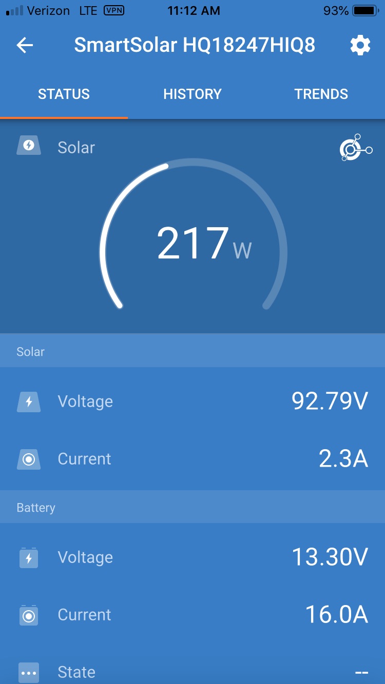

MPPT Controllersvoltage
image-1-1.jpg (115.2 KiB)
image-1.jpg (95.6 KiB)
snap1.jpg (32.3 KiB)
2 |3000

Up to 8 attachments (including images) can be used with a maximum of 190.8 MiB each and 286.6 MiB total.

5 Answers
simon-bernin avatar image
simon-bernin answered ·

Hi!

I have a few questions: Were you measuring the short cuircuit current when you had the 5 amps? What do you measure, when the controller is connected? Do the measurements from the controller and the ones of your multimeter match?

Not reaching the peak voltage is normal, especially in a hot area such as yours. Have you investigated the most suitable setup angle for your panels in your area?


Regarding the charging current, from your screenshot I can see that you already have a battery voltage of 13.3 V and start floating at 13.6 V. My controller starts lowering the charging current at 13.3 V, presumable to protect the battery health and doesn't take the max from what it could. Discharge your batteries further or increase the floating voltage to get more current at this point.


Best regards


Simon


2 |3000

Up to 8 attachments (including images) can be used with a maximum of 190.8 MiB each and 286.6 MiB total.

littlewiggler avatar image
littlewiggler answered ·

Measurements:

I removed the solar leads from the MPPT to do the measurement, then re-attached and took the screen shots.

I actually took them from 3 points in the solar wire change. Right after the panels and before they go down into the rv, then the cutoff switch, and then right at the connection point of the MPPT. All were the same voltage and amps.

If I measure on the screws that hold the wires in on the MPPT they are matching what the screen shots show. Thus my confusion.

Raw wire voltage and amperage is NOT the same as after they are attached to the posts, and what is shown in various monitoring screens.


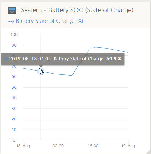
SOC on the batteries was down to 61%. These are lithiums, so not a whole lot of change.

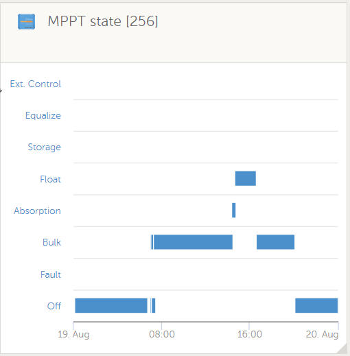
Charging state is showing Bulk.


Panels are on an RV, so not much I can do with angling them.


Outside temp was 82F when I did these measurements @ ~11am


I was using a Renogy Tracer 40 before the change to the Victron and Lithium batteries. I was showing 380-400 watts regularly before the swap.


2 |3000

Up to 8 attachments (including images) can be used with a maximum of 190.8 MiB each and 286.6 MiB total.

simon-bernin avatar image
simon-bernin answered ·

Hi, 61% seems pretty low, but the controller might still limit the current at 13.3 V there. I have no experience with lithium batteries.

If they were not connected to the controller, what where they connected to? You can't measure the amps without a load, you'll only get a short circuit current, which doesn't tell you what it could do with load. Amps are "pulled" by the load. You'd have to measure the current in series to the load, e.g. put your multimeter inbetween the plus cable right before your controller input. With load, the voltage drops, as well.


2 |3000

Up to 8 attachments (including images) can be used with a maximum of 190.8 MiB each and 286.6 MiB total.

littlewiggler avatar image
littlewiggler answered ·

Thanks!

Things like the difference the load makes is what I was hoping to learn (that it mattered while measuring).

I went out and measured right off of the terminals on where it connects (the screw terminals) while everything was connected.

Voltage readout on the Victron App was identical to the MM - in this test it was 82.59V.

Amps were different. I was reading 4.1 on the MM and only seeing 1.3A on the app.

Even more interesting. After a few minutes the voltage dropped to 60.22V and amperage went to 3.4A, but I was only reading 2.1 amps on the MM.


So the voltage is pretty dead on but the amperage is either high or low by 20-25% swings.

I am still trying to figure out why I have such low wattage - it looks like the amps are the issue. The batteries will not fully charge today. They should with 500 watts of possible power. After most of the day they are still only at 88%. Granted, I have had the MPPT disconnected and reconnected several times for about 1/2 an hour, but they still should have charged from 61%.

No clouds and temps in the low/mid 90's all day. Shadows are starting to cover the panels.

Head scratching and trying to figure out what to do.

4 comments
2 |3000

Up to 8 attachments (including images) can be used with a maximum of 190.8 MiB each and 286.6 MiB total.

simon-bernin avatar image simon-bernin commented ·

Did you really measure the current in between the solar plus cable going into the controller? Note that you can expect around 2000 - 2500Wh a day from your solar panels, but your batteries hold up to 3600Wh. So you can't charge them fully within one day if they were completely empty.

0 Likes 0 ·
1566168001643.png (8.2 KiB)
littlewiggler avatar image littlewiggler simon-bernin commented ·

I'll try tomorrow to rig something up to do this measurement.


0 Likes 0 ·
simon-bernin avatar image simon-bernin commented ·
0 Likes 0 ·
littlewiggler avatar image littlewiggler simon-bernin commented ·

I've read that post (and all of the others here on the Renogy batteries).

Float can't be turned off. It can be adjusted down to 12v, but not all the way off.

0 Likes 0 ·
Mark avatar image
Mark answered ·

I have read/scanned through your post and was hoping to get some further clarification about your concerns and also how any external measurments have been conducted - in order to better understand the behaviour and your comments.

But some feedback in advance;

1- Could you provide a simple wiring diagram sketch or photo showing exactly how you measured PV voltage and current?

I am am confused about your statement that PV current was measured while the PV wiring was disconnected from the MPPT, as there would be no current in this state since the PV is not under load.

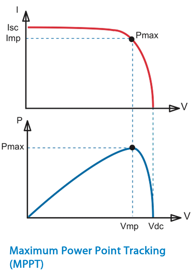
The PV voltage can be effectively regulated between the Voc (at the solar & temp conditions at the time) and 0V depending on the load that the MPPT applies to it. Somewhere in that range there will be a 'sweet spot' where the product of V x I = P is maximised - this is called the Maximum Power Point (MPPT or Pmp)


So when you were measuring current, did you actually complete the circuit back to the MPPT and just insert the multimeter in series with one of the PV cables OR did you effectively 'short circuit' the PV by directly measuring current by connecting the multimeter leads to both PV cables? (which would result in PV voltage = 0V)

2- The Pmp can also change quickly depending on solar condition, so the MPPT will always aim to be operating at the optimal point and periodically check to see if a better point exists.

So if you are ever conducting any external measurements / comparisons they would only be valid if they were measured simultaneously (with the PV cables connected to the MPPT and the MPPT controlling the load to optimise the power (not just voltage or current in isolation of each other)

3- It is unrealistic to expect close to max rated PV power, just because the sun is out. During overcast / winter times you might only get ~10 to 20% of max power. With fairly good sunlight and a semi clear day you might get ~40 to 80%. To get ~80 to 100% it really needs to be a near perfect day with very strong sun, clear sky and not excessive temperature.

Another point to note with wiring many panels in series is that if one panel or even one cell is even partly shaded then it can have a significant negative impact to the max power of the total array.

4- The MPPT will only operate at the mppt point when it needs to increase the battery voltage to the setpoint configured. So this would be always during bulk phase and also during absorption or float but ONLY if the voltage has dropped below the setpoint / target voltage for the particular charge stage.

When the battery voltage has reached the setpoint then the MPPT will purposly limit both the PV power and accordingly the charge output power to maintain the voltage setpoint, otherwise the battery voltage would just keep rising.

5- If you are having trouble achieving 100% SOC, it could be due to insufficient PV to BOTH recharge the battery AND power loads &/or MPPT charge settings &/or the BMV configuration.

It may well be that the SOC % as indicated by the BMV has 'drifted' away from the 'true' battery SOC % and that it has not been recently synchronised. There are various parameters in the BMV configuration to enable it to better track the 'true' SOC % and also enable it to synchronise periodically when the correct conditions present.

6- MPPT charge output / power can go fully to the battery or directly / fully to loads and any combination in between. So unless you have absolutely all loads properly disconnected (even the CCGX / monitoring equipment has a current draw), then don't expect the MPPT charge output to perfectly match what the BMV is measuring as flowing into to battery.


4 comments
2 |3000

Up to 8 attachments (including images) can be used with a maximum of 190.8 MiB each and 286.6 MiB total.

littlewiggler avatar image littlewiggler commented ·

Mark,

Thanks for the reply. Again, I am trying to wrap my head around how much different Victron is from Renogy. I had a 4 x 100W system in place for 4 years with flooded batteries. Switching to Lithium took me down a whole different rabbit hole and I added an inverter and BVM.

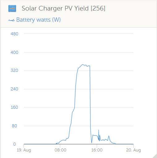
With the Renogy system I was seeing ~340-380 Watts regularly using their MPPT monitor and charger. Since the change I've yet to see more than 320W from 4 panels.

Answers:

1&2) As mentioned above, I measured with no load at the point of connection. I was making sure there was no loss due to cabling from the panels up to the MPPT connection. I took some measurements from the screw terminals after reconnecting them and observed the amp differences. I have a in line monitor I'll put in line on the solar side in a day or two.

3) Understood - again, I am seeing ~50Watt degradation from what the Renogy system was showing. It might be because those were flooded cells vs the LiPo's.

No shade on the panels from 9:30am to ~6pm on the last 2 days.

5) I can reach 100% regularly - did it again today. Today was like yesterday, only 5F hotter (98F), so in theory today's output should have been less than yesterday.

6) Understood.


Thanks for looking at this. My challenge is that I am good at ~350W output based on my usage history. I am not so sure I can get by with ~320. That is why I added a 5th panel for testing.

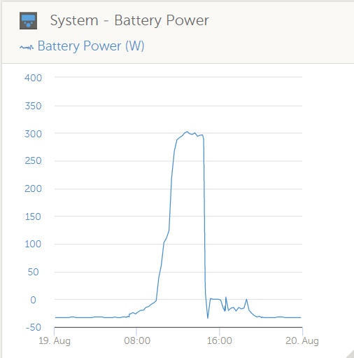
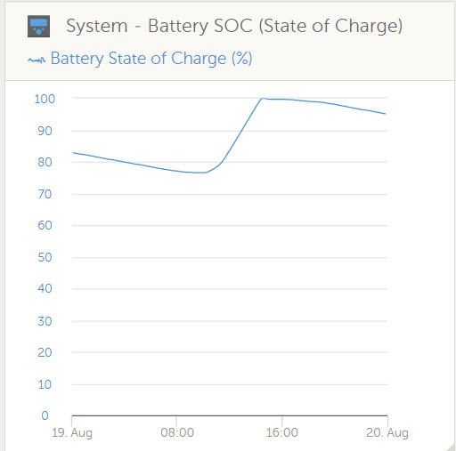
Graphs from Sunday (93F high - no clouds, winds less than 25mph):


Graphs from Monday (98F high same - clear, winds up to 25mph) - no changes to the system or location.


0 Likes 0 ·
snap2.jpg (23.9 KiB)
snap3.jpg (28.7 KiB)
snap4.jpg (31.1 KiB)
snap5.jpg (26.6 KiB)
snap6.jpg (23.0 KiB)
snap7.jpg (24.8 KiB)
snap8.jpg (25.8 KiB)
snap9.jpg (23.6 KiB)
Mark avatar image Mark ♦♦ littlewiggler commented ·

Hi @LittleWiggler, no problem - hopefully we can try to find a logical explanation for an concerns that you have.

Some responses to your feedback (sorry for slightly repeating a few points)...

1 & 2) If you measured VOLTAGE directly at the PV cables while disconnected, yes there will be no load (0A) and the voltage would be the open circuit voltage (Voc) possible with the solar conditions at the time. Just 'say' you measured 100V in this state - note that 100V x 0A = 0W...

If you measured CURRENT by connecting the multi-meter leads to the PV cables while disconnected, you HAVE just added a SHORT CIRCUIT LOAD, which is the actual multi-meter. As a result this would drag the PV voltage down to 0V. So 'say' you measured 5A in this state - note that 0V x 5A = 0W...

The key for the MPPT is to find the max power point by applying a charge load that optimizes the product of V x I = P, to get the most out of the current solar conditions. So the max power point will always be at a voltage LOWER than Voc and a current LOWER than Isc - but the POWER will be maximized.

So yes, even if the solar conditions were perfectly identical/unchanged you will see a difference when measuring PV voltage and current with the cables disconnected form the MPPT, compared to the PV voltage and current while the MPPT is in control.


3) Providing the MPPT is in BULK phase and battery voltage is BELOW the target absorption voltage, then it will always aim to provide max charge power to the batteries, regardless of the battery type. I would put any perceived difference down to different solar conditions / time of year / sun path vs solar panel angle / dirty panels / etc. - since the Victron MPPT controllers are very good at identifying the best MPP, even when multiple exist and also have excellent conversion efficiency.

If you really want to do a proper back to back (B2B) test then its normally advised to reset everything back to the original configuration to see if the initial results can be repeated again OR if some other variable has changed.

So if you want to investigate further than maybe try to hook up your original MPPT and see if you can replicate the results that you expect.


5) Good to hear, so it sounds like its more of an issue with insufficient PV yield to cover your daily loads, rather than a BMV setup / synchronization issue.


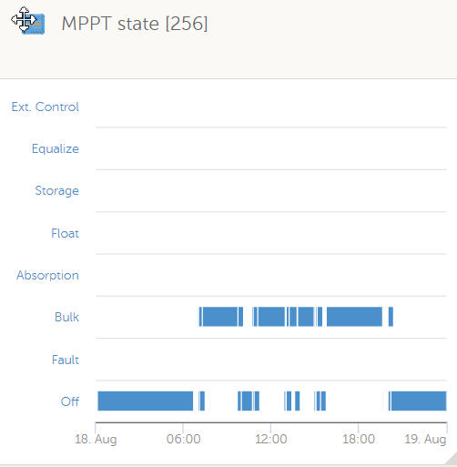
Regarding the 1st VRM attachment in your last response (MPPT state 256) - any ideas why the charger is switching between BULK & OFF state?

Is that you trying to manually reset the charger or something?

Is it maybe the battery internal BMS disconnecting the battery for some reason or a bad / intermittent connection somewhere?

Low PV voltage (below battery voltage) could explain this, but I thought that you have all solar panels connected in series, so after initial start up in the morning you should a good buffer with PV voltage...

0 Likes 0 ·
littlewiggler avatar image littlewiggler Mark ♦♦ commented ·

Mark,

Once again thanks.


I added a monitor to the incoming solar amps and voltage and it matches what the MPPT controller is stating.


It looks like I have some more information to decipher.

0 Likes 0 ·
Mark avatar image Mark ♦♦ littlewiggler commented ·

Hi Littlewiggler,

I'm very glad to hear that, please let us know if you have any more concerns.

Take all information with a grain of salt, and it's normally not a great idea to have 2 pieces of equipment measuring the same thing, as you will almost always have 2 slightly different results...

0 Likes 0 ·

Related Resources

MPPT Product Page

MPPT Error codes

MPPT 150/60 up to 250/70 Manual

Additional resources still need to be added for this topic