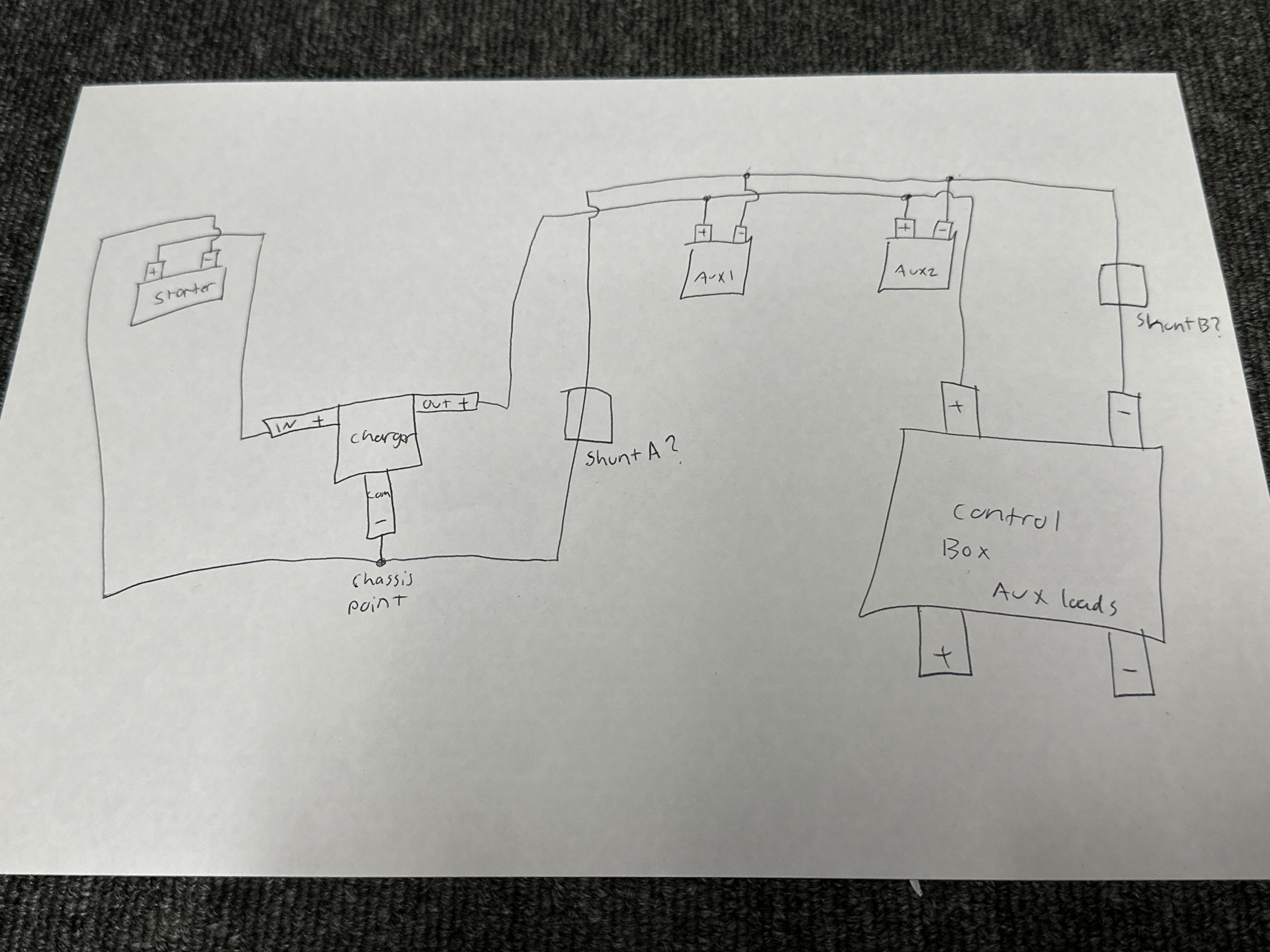
 Hi, just wondering where I would need to put the shunt in this diagram, I’m guessing either in either of the A or B spots I drew? Cheers
- Home
- Anonymous
- Sign in
- Create
- Spaces
- Grafana
- Node-Red
- Unsupported topics
- Questions & Answers
- Modifications
- Communauté francophone
- Deutschsprachiger Bereich
- Preguntas en Español
- Explore
- Topics
- Questions
- Ideas
- Articles
- Badges
question
Where should I put the shunt
Assuming aux1 and aux2 are batteries and you want aux battery SOC etc. , this isn't going to work. In position A it will measure charge, in position B it will measure loads. In neither position will it measure SOC correctly.
The shunt should measure all current into and out of the battery, while loads which bypass the battery bypass the shunt. As @Alexandra said single connection to battery negative from shunt.
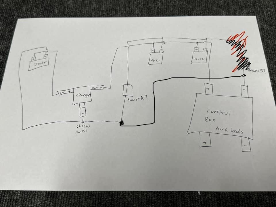
So at the batteries join the positives to a busbar which also has the charge positive and load positive and shunt positive. Join the battery negatives, connect combined neg to the battery side of the shunt. Connect load side of shunt to busbar with neg from charger, neg from loads, and ground/earth. Make sure starter battery shares the same ground/earth.
Alright thank you. Also wondering if this would work too then?
By B.
Always right by the battery you are trying to measure if it is for SOC with nothing on the battery terminal except the connection from the shunt.
question details
54 People are following this question.
