question

Kirk B avatar image
Kirk B asked

Negative AC input .... How so?

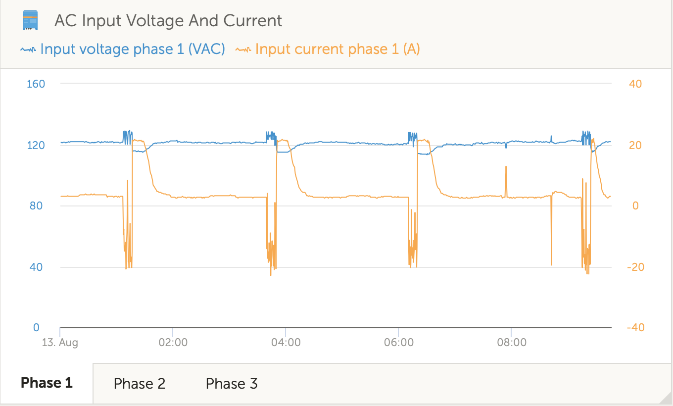
Twice now I have experienced a negative AC input. I'm sure it is happening more frequently and has just gone unnoticed. I have two multiplus 24/3000 inverters in parallel. I have defined two AC inputs. Shore power is connected to the master AC input. When there is a load (eg, Air Conditioner, water heater), I'm seeing the AC input go negative, a significant drain on my batteries which appear to be supplying power for both the AC Output and the suspicious AC Input (feedback???). After the load drops, the system appears to return to normal and recharges the battery bank. I have no assistants loaded and have not defined a country code for feeding back to the grid. How can this be???

MultiPlus Quattro Inverter Charger
2 |3000

Up to 8 attachments (including images) can be used with a maximum of 190.8 MiB each and 286.6 MiB total.

2 Answers
Kirk B avatar image
Kirk B answered ·

Daniël,


Yes, you read correctly, this is a parallel system. When I built the system I received sign off from you guys that defining two separate inputs was ok. However, and this might be on me, I was running split phase but due to limitations only having 3000va per leg. We moved over to a parallel setup to ensure we could pull more amps per leg. Essentially we have 3 air conditioners. 2 on one leg and 1 on the other. Parallel allows me to run any two of the 3. Where as, split phase restricted me to one AC per leg restricting the ability to run the two air conditioners that are on the same leg at the same time. Hope that makes sense :)

If the asymmetrical wiring on the AC input is indeed a problem, that is an easy fix.

Also, sorry no accurate diagram and pictures right now will be tough as we are traveling. Inverters are in a storage compartment that has a number of other items stored in front of my inverter / battery enclosure.

Thanks!

5 comments
2 |3000

Up to 8 attachments (including images) can be used with a maximum of 190.8 MiB each and 286.6 MiB total.

Hi Kirk,

Yes as in the documents: All AC and DC wiring must be symmetric.

So you'd need a transfer switch, or for the time being just use a plug to connect to either shore power or generator.

In a split-phase situation you can indeed use two separate inputs.

0 Likes 0 ·
Show more comments
Daniël Boekel (Victron Energy Staff) avatar image
Daniël Boekel (Victron Energy Staff) answered ·

Hi @Kirk B

This usually has to do with wiring issues.

Please read this document:

https://www.victronenergy.com/live/ve.bus:manual_parallel_and_three_phase_systems

6 comments
2 |3000

Up to 8 attachments (including images) can be used with a maximum of 190.8 MiB each and 286.6 MiB total.

Kirk B avatar image Kirk B commented ·

Thanks Daniël. I did follow that guide when I did the installation. I am however using only 1 breaker for the AC output but I would not imagine that would cause a back feed on the AC input.


Question: Am I really back feeding power on the AC input or is this just an artifact of something else? This seems rather dangerous and implies that the AC in and AC out are not isolated.


I added a second multi as my power needs exceeded my original design. Would I be better off selling the multi's and going with a Quattro?

0 Likes 0 ·
lucasnowak avatar image lucasnowak Kirk B commented ·

Hi @Kirk B,

I've got a similar issue with 3x Quattro in our installation.

Have managed to get to the bottom of the problem?

I've downloaded the logs and it looks Quattro is feeding power into the grid - you can see that by rising AC input voltage on a phase.

quattro_power_back.txt - best to open in excel.

@Daniël Boekel (Victron Energy Staff)

Any other things or settings that may be causing the issue?


0 Likes 0 ·
Daniël Boekel (Victron Energy Staff) avatar image Daniël Boekel (Victron Energy Staff) ♦♦ lucasnowak commented ·

Hi Lucas,

the same answer for you:

There are lot's of things that can go wrong when installing a parallel setup, that's why we have training days for installers, I might be able to give some meaningful answers, but I need some information first:

-a diagram of the system

-pictures of AC and DC wiring

-anything that might be of interest.

0 Likes 0 ·
Daniël Boekel (Victron Energy Staff) avatar image Daniël Boekel (Victron Energy Staff) ♦♦ Kirk B commented ·

Hi @Kirk B

What does '1 breaker on output' have to do with the document?

It is recommended to use one for both inverters (input and output)

There are lot's of things that can go wrong when installing a parallel setup, that's why we have training days for installers, I might be able to give some meaningful answers, but I need some information first:

-a diagram of the system

-pictures of AC and DC wiring

-anything that might be of interest.

0 Likes 0 ·
Kirk B avatar image Kirk B Daniël Boekel (Victron Energy Staff) ♦♦ commented ·

Daniël,

I re read that as one ac breaker per multiplus. I set it up as one breaker total on the ac output per your clarification. Now with that out of the way :)

Some observations on my system:

1. The negative feedback only occurs at higher input settings. Eg, does not occur at 20a, does occur at 24a when connected to shore power.

2. On the positive DC side, I’m using 2/0 from the battery bank (lifepo4 @24v / 400ah) to a 300a fuse->disconnect switch->busbar. From the bus bar I use 2/0 to each inverter. All symmetrical.
3. On the negative side I’m using 2/0 from the battery bank to a Victron battery monitor shunt->busbar. Then 2/0 to each inverter. All symmetrical.
4. I configured two inputs in vebusconfig. Eg, shore power and generator. So, shore power is connected to only one multiplus. Likewise, the generator is connected to only one multiplus. The generator is configured as a 20a input just below the input amperage where I seem to have issues.

5. When on shore power, I’m connected to an RV campground with a 30ft power cord so there is additional cabling when On shore power.

6. On the ac output side, I‘m using 4ft of 8awg per inverter into a breaker box where the two outputs are tied together And pass through a 50a breaker. The combined output then goes through 6awg to my rv’s Main panel.

Could the two defined inputs be an issue since at any given time only one of the inverters in this parallel system is receiving AC input?

In your opinion is the feedback issue a result of a problem on the DC side or AC side? It would be helpful to narrow the scope if possible.


thanks again!


kirk

0 Likes 0 ·
Daniël Boekel (Victron Energy Staff) avatar image Daniël Boekel (Victron Energy Staff) ♦♦ Kirk B commented ·

Hi @Kirk B

Do I read correctly that you are using a parallel setup with the inputs not connected in parallel?

Or do you have a split-phase setup?(so not parallel)

Please answer the questions I've asked earlier, otherwise there will be more confusion:

-a diagram of the system

-pictures of AC and DC wiring

0 Likes 0 ·