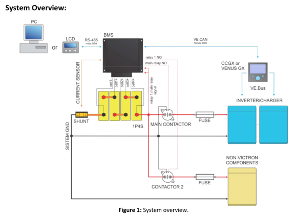
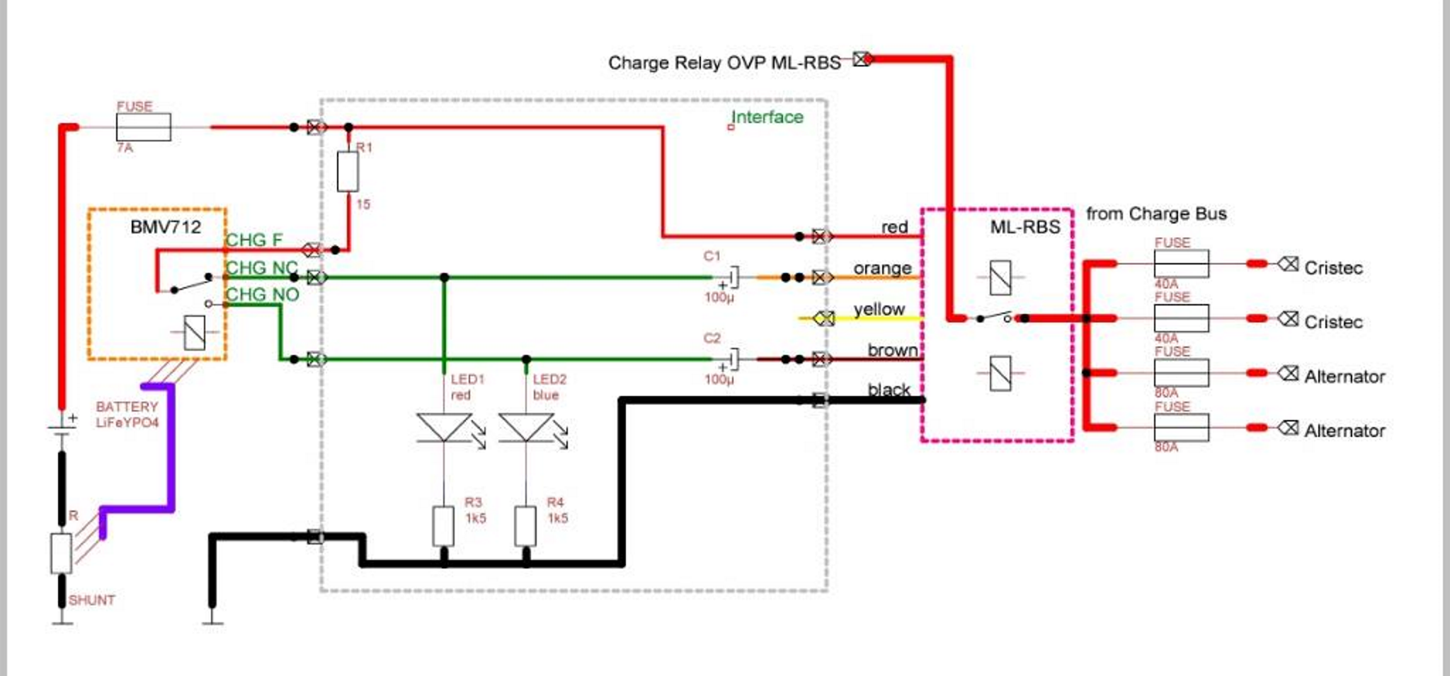
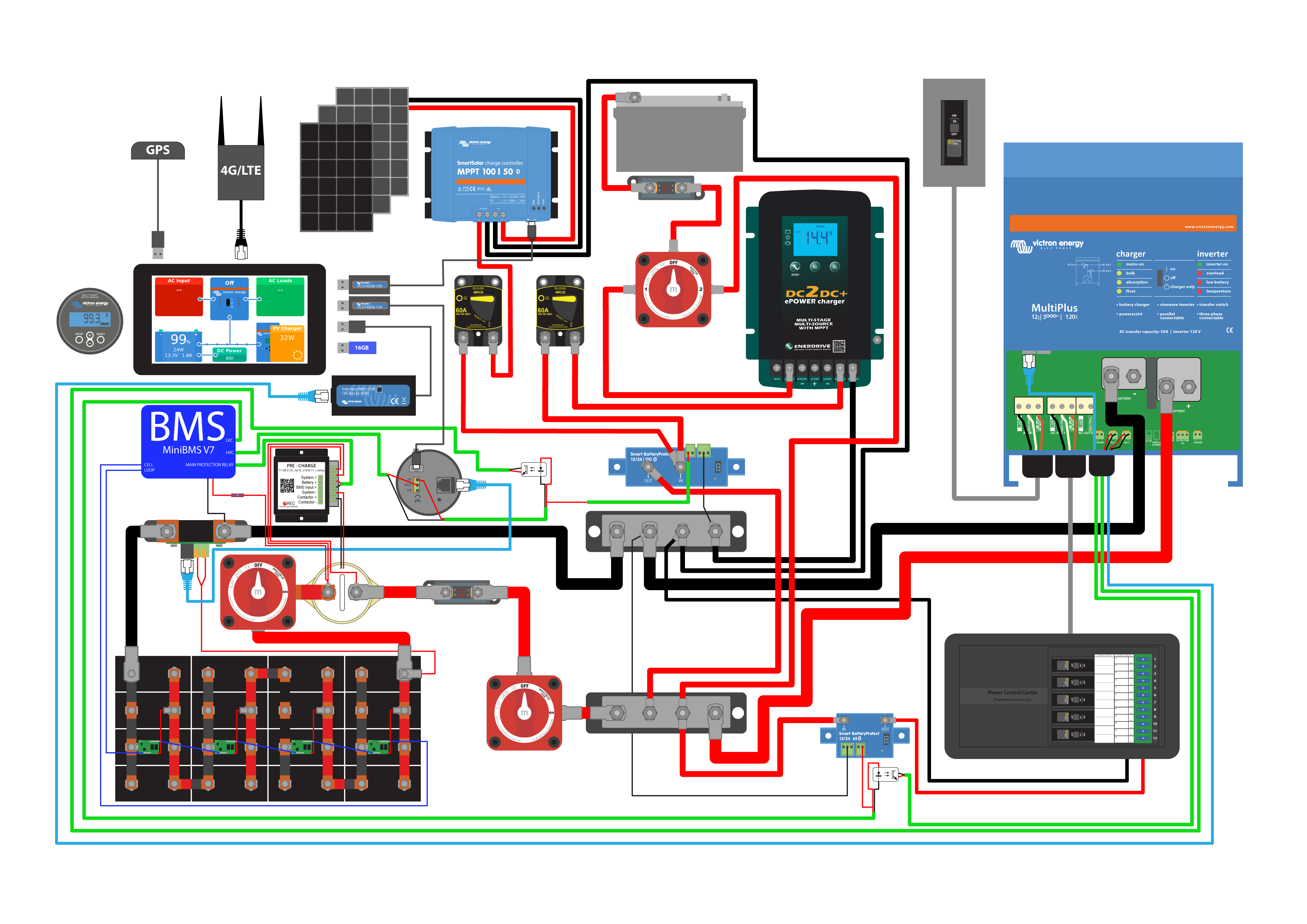
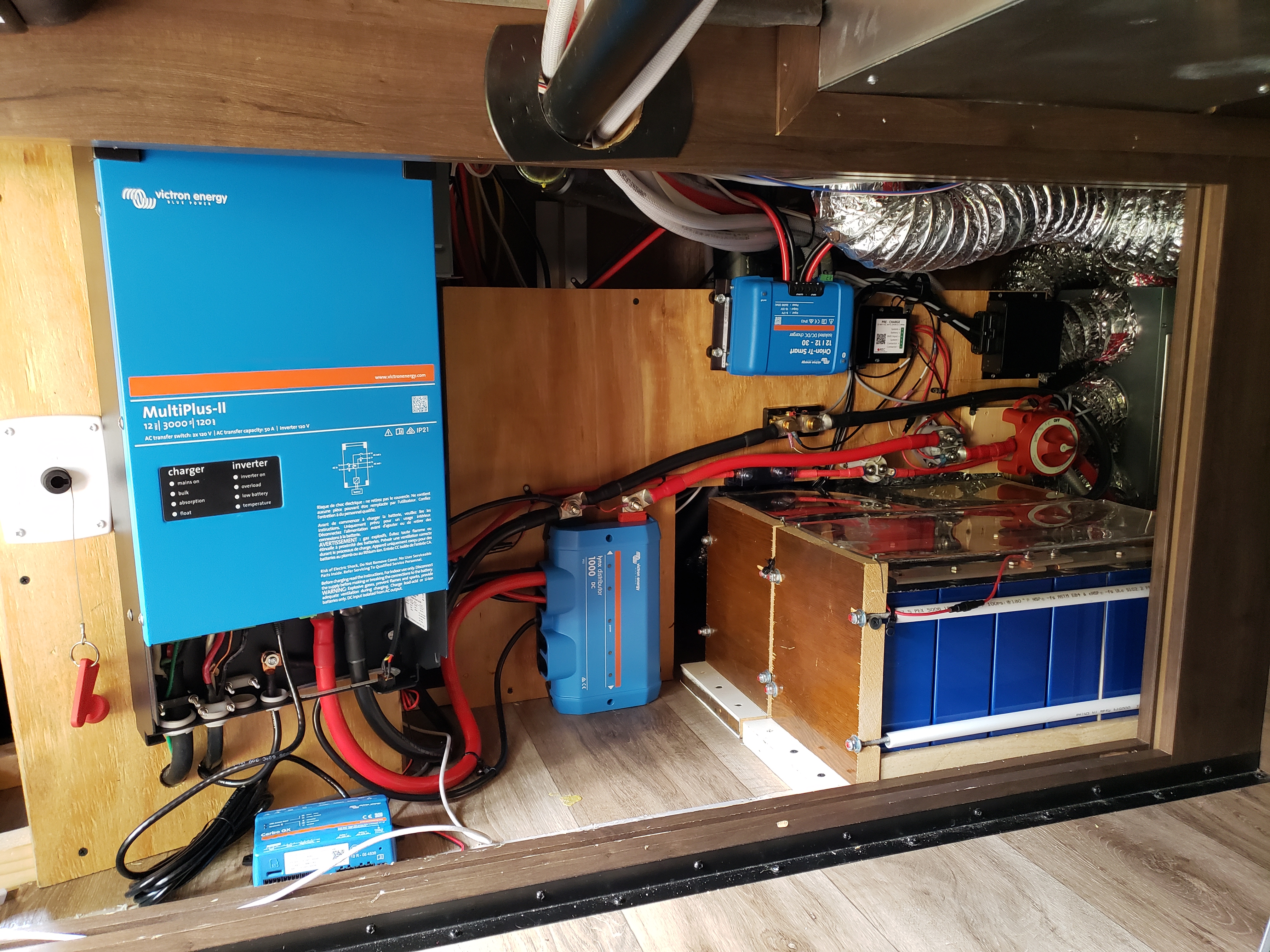
This new version of "REC-ABMS for Victron CCGX" communicates with a GX Device using CAN. It sends Max Charge Current & Voltage and Max Discharge Current along with Battery Voltage, Temp & SOC. The GX Device uses DVCC & SVS to control all Inverter / Charger & MPPT Solar controllers to comply with the charging / discharging limits. Ok, so that sounds good, huh? But I also want to have contactors set to voltage levels in case the CAN bus goes down.
The previous version of the BMS suggested just the traditional two contactors - HVD & LVD to provide High Voltage Disconnect of the charge bus and Low Voltage Disconnect of the DC load bus.
But this version offers a Main Contactor for both HVD & LVD for Victron inverter / charger devices. And another Contactor expected to be used for HVD on non-Victron Charging sources. And though it is not shown in this diagram, I am sure they expected a third contactor for LVD to disconnect DC Loads.

Is this genius or overkill?
I questioned the new functionality, and the manufacturer offered to disable it to make it functionally equivalent to the old version. But I am an Engineer, so I tend to think "here is a Solution, now lets go find a Problem..."
Any thoughts appreciated.....
Andy
----
P.S. And....
I was expecting the fail-safe MultiPlus Inverter/Charger control to be made with a Charge Control signal to AUX1 and Discharge Control to T1 with the Assistant loaded "Two wire BMS (016A)"...
But they are suggesting Charge Control using the Assistant "Input Current Limit Control (0142)" and the AUX1 signal. And programming the Inverter's DC Input Low Shutdown voltage for Discharge Control.
Some REC users I have enjoyed reading before: @paulb @drmi @Boekel @Poppycock @Hakon Ingvaldsen @Eirik @Ceri.w


