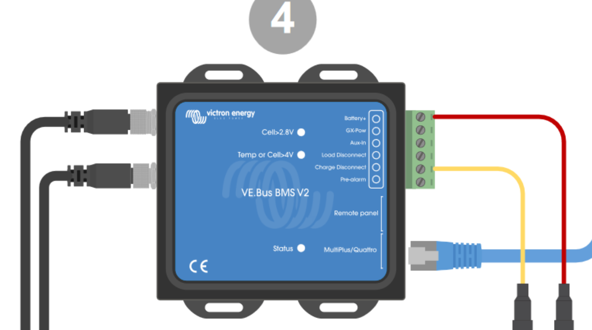
Hi there, Looking for some help on the 2 conflicting diagrams in the Orion-Tr smart user booklet.
I have 3 x 200Ah Victron Smart LiFePO4 batteries connected to a Quattro 2, utilising a VE.Bus BMS V2 for control (I have a Cerbo GX for monitoring) This is all fine charging from the grid and from 1700W solar via 2 x 100/30 Victron MPPT as one VE Direct cable from each MPPT to the Cerbo takes care of shutting down the charging from the Solar to protect the LiFePO4 batteries.
I do need however to be able to charge the lithium bank from the engines when running as an additional redundancy.
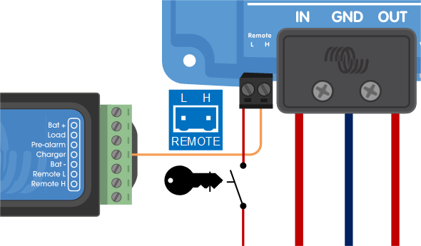
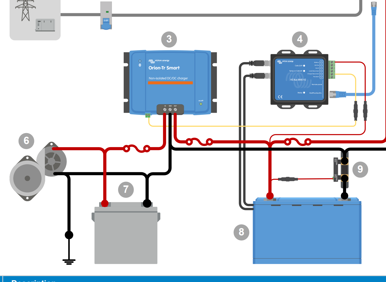
I have 4 x Orion Tr-Smart 12/24 - 15 units daisy chained together and need to connect this to the VE.Bus BMS V2 to enable charging shutdown for protection of the lithium.
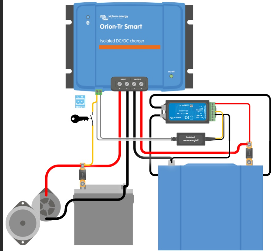
I also need to enable the charging ONLY when the engines are running, when the alternators are producing power, but the VE.Bus BMS V2 can still shut the Orions down if required to protect the batteries.
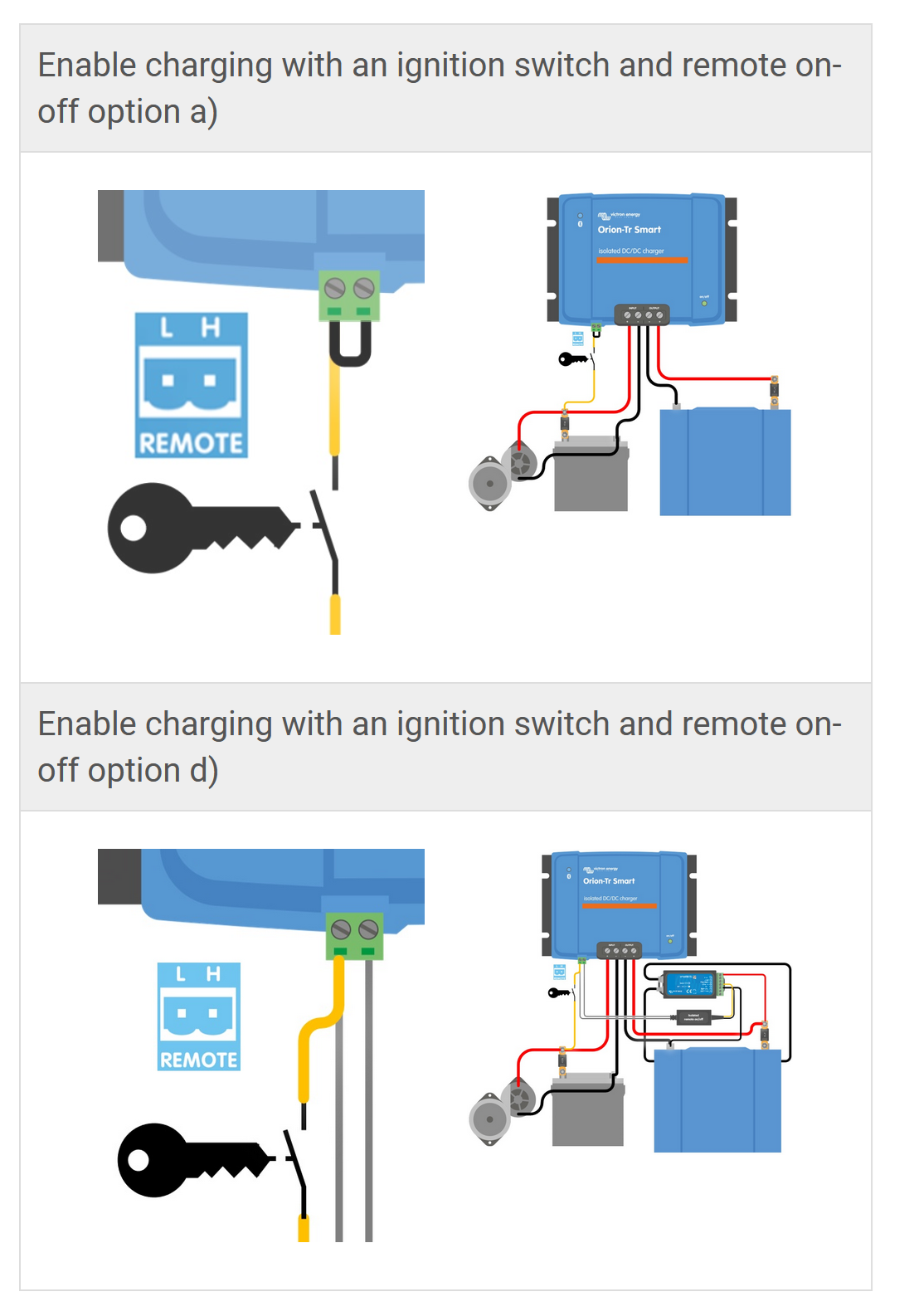
The 2 diagrams in the manual contradict each other, one showing L-Pin wiring connected with jumper to H-Pin with a yellow wire to ignition, I am told this will destroy the unit however....
The other diagram is the H-pin which shows a live feed from the input via the ignition switch to the H-Pin. I can't find anything though that clarifies the VE.Bus BMS V2 wiring in conjunction with this.
Any advice much appreciated!!

