question

zucca avatar image
zucca asked

Can we please help Victron to solve the Lynx Shunt wrong voltage problem?

After reading this

https://community.victronenergy.com/questions/122850/lynx-shunt-wrong-voltage-value.html

I decided to create this new thread to give a better overview about the above problem to Victron.

First things first, IMHO, it is NOT a show stopper for us users. It is just something to consider and adjust in (the shunt/system) settings if necessary. According to my investigation is only an offset. Nothing critical just and irritation

- Problem Description:

Lynx Shunt reports to the VE.CAN (what you will see then in VRM or Remote Console) a LOWER voltage reading than the one provided by other Victron devices (like MPPTs and Inverters). This is also confirmed by external measurement with multimeters.

- Details

1) Only 48V System seems to be affected by this problem

2) The max offset reported between shunt voltage measured and "the rest" is about 500mV

3) No solution is officially provided by Victron

4) No DC voltage recalibration is possible on the Lynx Shunt

5) Some users ended up swapping the Lynx Shunt with the SmartShunt, since it costs less and perform better.

6) For ESS System the MPPT/Inverter DC Voltage is shared, see here (thanks to the immense @Some-user)

https://community.victronenergy.com/questions/242290/mppt-in-ess-doesnt-show-ess-state.html?childToView=244246#comment-244246

this is also why the DC voltage there is the same across those devices.

- How do I know if my Lynx Shunt is affected by the above problem?

The simplest and most effective way is to create a custom widget in the VRM plotting the Lynx Shunt voltage and the "DC system voltage". If you will see two lines with the same shape and the shunt voltage is lower, then welcome to the club.

Example of the above widget:

2024-01-19-22-21-36-zuks-sc-home-vrm-portal-mozill.jpg


The more complicated way is to download the .xls file with the raw data from VRM and do some statistic on them.

Here below you can see some of my DC voltage values:

1705724134758.png

Average: the average of the DC voltage reported without the Lynx Shunt one

delta AKA Lynx Shunt error: the above value minus the Lynx shunt DC voltage.

Here below the statistics of the Lynx Shunt error DC voltage error:
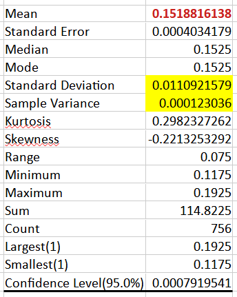
1705724096513.pngWith such a small variance, I am sure the error is just a constant offset.

In other words my Lynx Shunt ALWAYS reads about 152mV lower than the rest.

- Immediate countermeasures

Lower the affected DC Voltage setting by the know offset error.

Example with 200mV offset:

I want 100% SoC at 55.5V, enter the value 55.5-.2=55.3V

- What we user can do to help Victron:

Report the problem with the Lynx Shunt serial number.

Here the list:

152mV, SN 1705724302126.png

- What Victron can do to solve this problem:

The most effective and elegant way it to provide a FW update with the new feature to calibrate the Lynx Shunt DC voltage. Mostly copy paste of what is already implemented for the DC current measurement.


Many thanks to all users who reported the problem first, expecially @Michael Schmidt

lynx shuntbattery system voltage
2 comments
2 |3000

Up to 8 attachments (including images) can be used with a maximum of 190.8 MiB each and 286.6 MiB total.

kevgermany avatar image kevgermany ♦♦ commented ·
I've reported it to Victron for you.
1 Like 1 ·
zucca avatar image zucca kevgermany ♦♦ commented ·

Thanks, I have lots of calibrated EE equipment to perform deeper analysis, for example Keithley DMM7510 and Keysight MSOX3104T.

I can also test a beta Firmware for the Shunt.

Just let me know if I can help in anyway...


0 Likes 0 ·
9 Answers
mvader (Victron Energy) avatar image
mvader (Victron Energy) answered ·

Hey @zucca , this is just to confirm that your message made it to us (Victron). Next week we'll check on a few units from stock to see for ourself.

5 comments
2 |3000

Up to 8 attachments (including images) can be used with a maximum of 190.8 MiB each and 286.6 MiB total.

zucca avatar image zucca commented ·

Roger Sir! I would love to take a plane, come to the Netherlands and help you out!

1 Like 1 ·
urs4-2008 avatar image urs4-2008 commented ·
How is the testing going, @mvader (Victron Energy) ?


0 Likes 0 ·
martin-fi avatar image martin-fi commented ·
Any News ?
0 Likes 0 ·
urs4-2008 avatar image urs4-2008 martin-fi commented ·
No. We need the option to calibrate this, Victron
0 Likes 0 ·
urs4-2008 avatar image urs4-2008 commented ·
@mvader (Victron Energy) Could you please update us?
0 Likes 0 ·
giampaolo avatar image
giampaolo answered ·

My Lynx Shunt has the same problem - 150 mV compared to the readings made by multiplus and external voltmeter.

SN 0286085 HQ2243VNJDH

2 |3000

Up to 8 attachments (including images) can be used with a maximum of 190.8 MiB each and 286.6 MiB total.

Constantin Zaharia avatar image
Constantin Zaharia answered ·

ok, you are right, are differences, but what is the reference? the charger? the battery?

an offset setting for each block will be great. because also voltages differ on each installation, considering the cables used, length of the cables.

The voltages are different for each node with small differencesvrm-voltages.pngvrm-voltages.xlsx


vrm-voltages.png (69.9 KiB)
vrm-voltages.xlsx (39.5 KiB)
2 |3000

Up to 8 attachments (including images) can be used with a maximum of 190.8 MiB each and 286.6 MiB total.

zucca avatar image
zucca answered ·

@Constantin Zaharia

Due to Ohm's law, an offset for each block does not make sense.

In other words there is not a unique DC voltage in a Victron system, since not only the cables (lenght, diameter) but also the current is playing a role (like in the yellow line posted in your graph above).


The reference is the voltage measured at the Lynx Shunt bus bars with a calibrated voltmeter.

According my measurements and the one of the others users, the Inverters and MPPT are much more accurate than the Lynx Shunt, so that they can be used as a rough "reference", without a calibrated voltmeter.


Moreover, in my system I used short and big cables for the DC, so the ohm laws voltage drifts are much less than the Lynx shunt error offset, and I proved it with my statistical analysis.

2 |3000

Up to 8 attachments (including images) can be used with a maximum of 190.8 MiB each and 286.6 MiB total.

urs4-2008 avatar image
urs4-2008 answered ·

My shunt is about 0,5V too low as well. Please give us at least a calibration option in VRM by a firmware update.

1709198093814.png


1709198093814.png (10.6 KiB)
2 |3000

Up to 8 attachments (including images) can be used with a maximum of 190.8 MiB each and 286.6 MiB total.

richies avatar image
richies answered ·

Same here: -190 mV deviation! Serial No: 0207517 HQ2150746V2

2 |3000

Up to 8 attachments (including images) can be used with a maximum of 190.8 MiB each and 286.6 MiB total.

zucca avatar image
zucca answered ·

Maybe now that Victron released the new FW for the Lynx Smart BMS

https://professional.victronenergy.com/news/detail/245/

maybe they have now the men power to address this issue with a new Lynx Shunt FW.

Let's hope!

I am sure the low level engineers, mvader included, are with us and would be able to solve this in 10days top...

My guess is somebody at Victron management is still thinking about the best strategy with shining .ppt on how to solve this voltage offset irritation, so please:

We weten dat de ingenieurs van Victron de beste zijn! Laat ze dit alsjeblieft oplossen!
2 |3000

Up to 8 attachments (including images) can be used with a maximum of 190.8 MiB each and 286.6 MiB total.

coulombiq avatar image
coulombiq answered ·

Hi Victron,

Brand new system set up August 2024.

Lynx details:

1724903151882.png

Multiplus Details:

1724903412900.png


Voltage error details:

1724903346607.png


This post was created 8 months ago Victron. How long until there is a fix for what is an expensive product?

Thanks,


1724903151882.png (14.1 KiB)
1724903346607.png (95.2 KiB)
1724903412900.png (20.9 KiB)
2 |3000

Up to 8 attachments (including images) can be used with a maximum of 190.8 MiB each and 286.6 MiB total.

Arno Broeders avatar image
Arno Broeders answered ·

Here too, between 150 and 350mV difference between shunt and multiplus.

1724949283223.png


A calibration possibility would be great to middle this out.

My first thought this is due to the voltage-drop on the cable between the lynx distributer and the multiplus. At 12:00 my DC chargingcurrent is 58 Amp and the Voltage difference between shunt and multiplus is 310mV, see the graph above. My Lynx and Multiplus are connected by 2 50mm2 cables in parallel and 90 cm in length. Now I write this down, this makes no sense. If it would be voltage drop on the cable, the multiplus and shunt lines in the graph would be crossing when going from charging to discharging the battery and this doesn't happen.


1724949283223.png (36.4 KiB)
2 |3000

Up to 8 attachments (including images) can be used with a maximum of 190.8 MiB each and 286.6 MiB total.

Related Resources

Lynx Shunt VE Can online manual


Additional resources still need to be added for this topic

Additional resources still need to be added for this topic