Hi all,
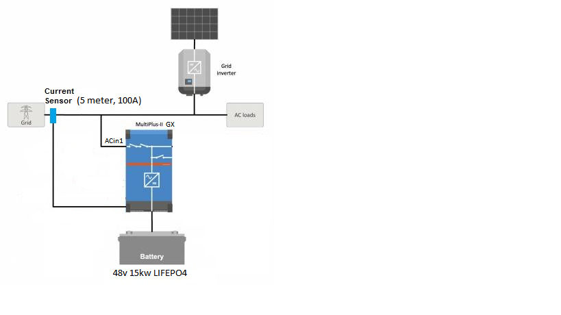
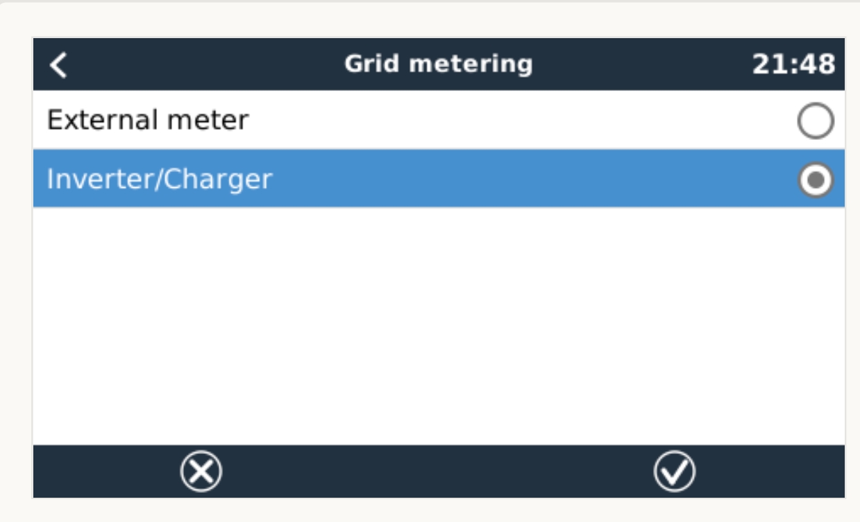
Im setting up a Multiplus II GX , running ESS assistant. My system is wired in parallel configuration, as pictured below. After trawling through many posts on the forum, im still non the wiser if this configuration will work. Some have said you definitely need a grid meter ( et112 ), and some have just used the CT. So ive rolled the dice and went with using just the victron 5 meter 100A CT Clamp. Well, after a lot of mucking around, i haven't been successful to get the Multiplus 2 to behave as it should.
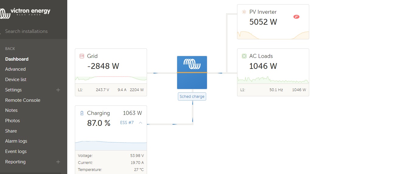
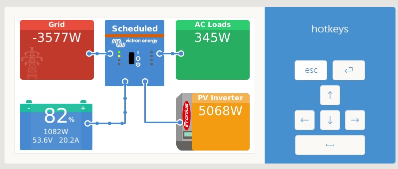
When the MP is booting up from first switch on, it does all the relay tests, and then attempts to connect to the grid. Now, if my AC coupled Fronius Inverter is outputting more than the loads are consuming, ( excess feeding into the grid ) the MP fails to connect to the grid, does the relay test again, and repeats this cycle. However, if the PV inverter is not producing more than is consumed by the loads, (so not feeding back into the grid) the MP will boot up and connect to the grid.
If i put the PV inverter outside of the CT clamp, the MP is happy, regardless of PV generation. But the problem i have then, is the MP wont use the excess PV to charge the battery.
Even though the Fronius sends its generation figures to the MP via TCP, the MP doesnt do anything with those figures. I think the MP has to 'measure' the flow of current by means of a grid meter.
So before I run out an buy a ET112 grid meter, i wanted to hear if anyone has had success with just the CT clamp in a grid parallel system with AC coupled PV.
Running firmware: 3.13 for the GX, 508 for the VE bus.
External current sensor 'checked' in VE configure
Feed-in excess PV is 'on'


