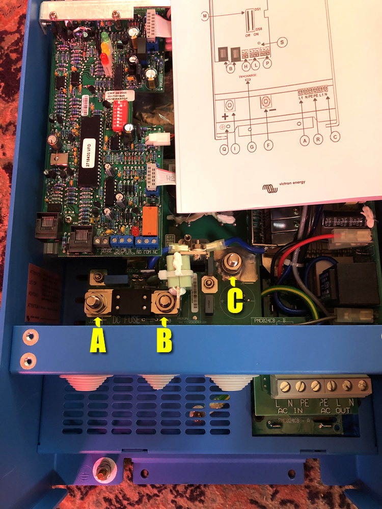
Attached is a photo I took of the inverter where I've labeled three studs as A, B, and C. I assume that A is DC+ since there's a plus sign on the PCB, but is B the negative, or is C? And then what's the extra stud for? The manual doesn't help.
- Home
- Anonymous
- Sign in
- Create
- Spaces
- Grafana
- Node-Red
- Unsupported topics
- Questions & Answers
- Modifications
- Communauté francophone
- Deutschsprachiger Bereich
- Preguntas en Español
- Explore
- Topics
- Questions
- Ideas
- Articles
- Badges
question
MultiPlus Compact 24/2000 battery connections confusion
inverter.jpg
(299.3 KiB)
Comment
1 Answer
There is a fuse conected between A and B
connect Positive to A in your Photo and Negative to C in your Photo
question details
10 People are following this question.
