question

saskak avatar image
saskak asked

smart solar mppt temperature compensation flipped (- to +)?

I have a very simple system with a victron smart shunt 500A, victron smartsolar mppt 100/30, 24V battery bank (2x FLA C20 100Ah), Victron Energy Phoneix 24V 1200VA inverter and 2x 340W panels connected in parallel. All connected via victron VE direct cables to a PI3 (VE.direct to USB).

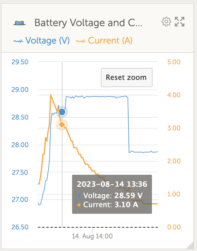
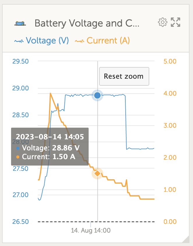
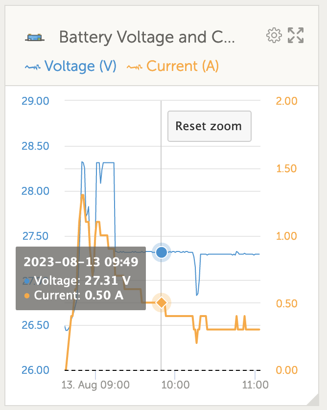
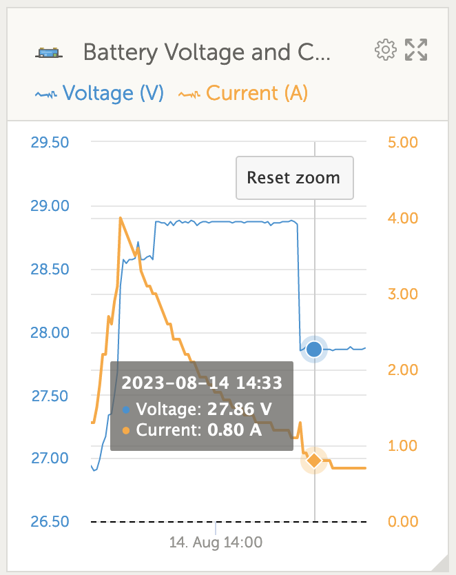
In the victron connect app I have temperature compensation set at -32mV/C (negative sign), as -16mV/C per battery was the recommendation for my FLA 100Ah battery (Banner). Yesterday the temperature in where the mppt is was ~18C, so lower than the 25C for the temperature compensation within the mppt. My absorption and float settings are 28.60V and 27.60V respectively. The absorption voltage held by the mppt was ~28.30 and float at 27.30, so lower than the settings as if the temperature is much higher than 25C.

This is rather odd, as the voltages have to be higher when temperature is lower than 25C. Today I disabled the temperature compensation (-32mV/C) and the mppt was holding the batteries at exactly 28.60V. Further, I put the temperature compensation at 32mV/C (positive sign) and low and behold, the mppt was holding the absorption voltage at ~28.86 and float at ~27.86. The temperature at the beginning of the day was probably ~17C, so 25C-17C = 8C * 0.032mV/C = 0.256 + 28.6 = ~28.86V.

All of these suggest that the sign for the temperature correction is flipped and it should not be negative, but positive. The firmware version of my smart solar 100/30 is 1.61, latest for the device.

Am I missing something or there is something else going on? I read the manual 5 times by now and searched the whole victron community for these positive/negative signs. There was a post back in 2020 (https://community.victronenergy.com/questions/71462/smartsolar-temperature-compensation-changes-voltag.html) about this and reporting exactly the same issue. This is as if someone in the algorithmic side of things multiplied by -1 somewhere and the manuals are not changed accordingly.

I also had a temperature sensor wired to the smart shunt and that did not change anything with respect to the signs. I have uploaded the photos of the values from my VRM portal.

Any help is more than appreciated.
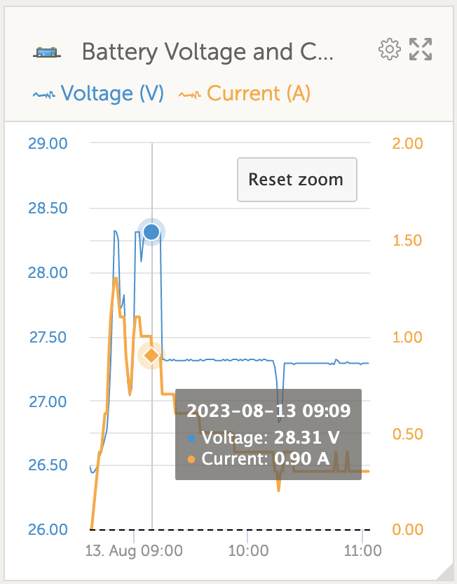
absorption-minus-32mv.pngAbsorption at -32mV/C, 17C at start of dayfloat-minus-32mv.pngFloat at -32mV/C, 17C at start of dayabsorption-temp-comp-off.pngAbsorption, temp compensation OFFabsorption-plus-32mv.pngAbsorption at +32mV/C, 17C at start of dayfloat-plus-32mv.pngFloat at +32mV/C, 17C at start of day
MPPT SmartSolartemperature compensation
5 comments
2 |3000

Up to 8 attachments (including images) can be used with a maximum of 190.8 MiB each and 286.6 MiB total.

kevgermany avatar image kevgermany ♦♦ commented ·

Please try updating the MPPT firmware.

0 Likes 0 ·
Show more comments

Hi @saskak

Do you have DVCC enabled on Venus on the PI3?

Do you perhaps also VE.Smart networking enabled on the MPPT and the SmartShunt (which you should not have enabled when DVCC is enabled on Venus)?

When you connect with a phone to the MPPT, what does it report as temperature?

Kind regards,

Thiemo van Engelen

0 Likes 0 ·
Show more comments
2 Answers
Thiemo van Engelen (Victron Energy staff) avatar image
Thiemo van Engelen (Victron Energy staff) answered ·

Hi @saskak

What might be happening here is that the internal temperature measurement of the MPPT does not match the battery/ambient temperature and the MPPT actually thinks that it is > 25 degrees. It should be ok when you add a temperature sensor to the SmartShunt and either add the MPPT and the SmartShunt to the same VE.Smart network or enable DVCC on the PI3. Either one of these methods allows the MPPT to receive the temperature measured by the SmartShunt.

Kind regards

1 comment
2 |3000

Up to 8 attachments (including images) can be used with a maximum of 190.8 MiB each and 286.6 MiB total.

saskak avatar image saskak commented ·

Many thanks for the follow up, appreciated. I had a temperature sensor wired to the smart shunt, but that did change the +sign for the mV and the behaviour. I did not have DVCC on at the time, so probably I would need to check it with the DVCC on and temp shaing to be certain.

0 Likes 0 ·
saskak avatar image
saskak answered ·

Just to confirm that when a temperature sensor is plugged in the Smart shunt and shared via the DVCC everything works as it is supposed to, i.e. the -32mV works. The DVCC points to and is sharing the temp sensor from the Smart shunt.

Perhaps the internal temp sensor of the MPPT does not quite work as intended (needs positive sign mV correction) or is faulty. I have two MPPTs, so I doubt both internal temp sensors are faulty.

If anyone has the same problem, get an external temp sensor wired to the Smart Shunt. That works with DVCC on. My previous tests with a wired temp sensor without the DVCC did not work, i.e. needed +32mV. Many thanks indeed for all the answers and help in this thread, more than appreciated.

5 comments
2 |3000

Up to 8 attachments (including images) can be used with a maximum of 190.8 MiB each and 286.6 MiB total.

tomas-arthuzzi avatar image tomas-arthuzzi commented ·
How did you get to set it to -32mV? Mine goes just to -30mV.
0 Likes 0 ·
JohnC avatar image JohnC ♦ tomas-arthuzzi commented ·
@Tomas Arthuzzi

The max Temp Comp you can set is limited to -5mV/cell/degC. So for a 6 cell 12V battery the limit is -30mV. 24V and 48V batts can go higher of course.

If you have 12V batts and need more, I'd suggest you check your info sources. I've never seen a batt maker suggest more than that 5.

0 Likes 0 ·
tomas-arthuzzi avatar image tomas-arthuzzi JohnC ♦ commented ·

Hi @JohnC, thanks for your reply!

Now I've era;ized that her battery is in 24V.

But anyway, I did double checked the manufacturer's manual and it really says 0,033V per Cº above and below 25º. I've attached an image. (it's in Portuguese, but its pretty easy)


screenshot-2024-02-28-at-012456.png


Not sure what to do, so I set it to -30mV, to get as close as possible. Any tips?


0 Likes 0 ·
JohnC avatar image JohnC ♦ tomas-arthuzzi commented ·
@Tomas Arthuzzi

Yeh, most unusual. Just use the max -30 mV. In the washup these figures are fairly rough, most makers use round figures at the cell level, like 3 or 4 etc. Occasionally a 0.5 thrown in when they can't make up their mind. Then they get converted from C to F and issue specs to decimal places of mV over a whole battery. Unnecessary. If you're worried though, just compensate your target Absorb and Float setpoints for worst conditions.

0 Likes 0 ·
tomas-arthuzzi avatar image tomas-arthuzzi JohnC ♦ commented ·
Thanks one more time!


I believe I'm fine with the -30mV setting.


Cheers!

0 Likes 0 ·

Related Resources

MPPT product page

VictronConnect manual

PWM or MPPT

MPPT calculator

MPPT codes

Additional resources still need to be added for this topic