question

ossi avatar image
ossi asked

ESS (AC DC coupled) "Feed-in excess solar charger power" not full potential

Hi

i running a ESS (MultiGrid 48/3000 FW459, VenusGX FW v2.31with EM24) with AC Coupled third party PV Inverters (via ET340 and ET112) and a Smart Solar 150/35 v1.39 and a BYD B-Box 5.0kWh. (DVCC enabled, SVS disable, Smartsolar has BMS controlled)

The DC Coupled PV system is oriented south and could be enlarged by approx 900 Wp, since currently only 1,8kWp is installed. Maximum charge power to battery is limited at 2000W fixed due to the 35 Amps - i know ;).

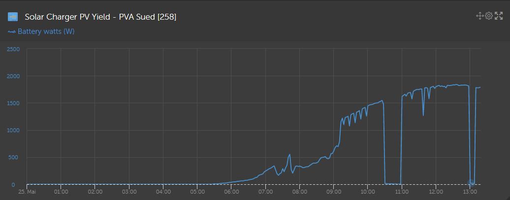
In the ESS Settings I enable " Feed-in excess solar charger power" but soon i discovered the the typical behavior of the system was to charge from the East oriented AC Coupled inverters, which means, the the battery is full, sincce there is enough excess. But the south orientated DC coupled PV System was dearted by over 50% due to battery being at SOC 100%, even with the enable option of "feedin excess DC Power". Over have of the production of the south oriented DC coupled PV is derated (see pic attached, redline is potential solar production).


To prove my hypotheses i changed the ESS Setpoint to activly discharge the battery into the grid, thus a lower SOC than 100% is realized. this enables the BMS controlled Smart Solar to use the full potential of the PV system. (previously 340W production goes up to 900W Production).

See my screenshots and notes

ESS Feed-in excess solar charger power - not full potenial.pdf


Conclusion:

I presume that the Mutligrid doesnt discharge/feedin as much power as the full potential of solar available on the DC side.

I would presume that the voltage Gap between SmartSolar and Multiplus isn't high enough for Multi to discharge the battery more but to keep it at 100% and though making it possible for the SmartSolar to feedin more of his potential solar power.


So propably i will not add any more Modules to the Smart Solar or install another SmartSolar, but install another PV Inverter AC coupled.


If anybody has the same Issue please let me know!

If anybody has an idea how to optimize the use of the DC coupled Solar to feed into the grid, please let me know! I thought already of an external PLC writing the ESS Setpoint into the Modbus register, to actively reduce the SOC during the daytime, to make more use of the DC coupled PV System.


THX

BR

Ossi

ESSchargerfirmware updatemultigrid
2 |3000

Up to 8 attachments (including images) can be used with a maximum of 190.8 MiB each and 286.6 MiB total.

6 Answers
ossi avatar image
ossi answered ·

To me it seems like the V2.4~34 released today is design to solve this issue!

https://community.victronenergy.com/questions/31299/venus-os-v24034-available-for-testing.html


*Change log*


After only one day (low irradiation) it seems like the fix is working so far:


My recommendation would be to try and test the release candidate if have have problems with this issue (feedin excess Solar). But keep in mind these are beta versions, which are not intended t o run a customer systems.


BR

Oliver


1570794864435.png (96.3 KiB)
1570795102483.png (74.4 KiB)
2 |3000

Up to 8 attachments (including images) can be used with a maximum of 190.8 MiB each and 286.6 MiB total.

hanszwicky avatar image
hanszwicky answered ·

I found a solution that seems to be working for me: https://community.victronenergy.com/questions/237470/cerbo-gx-bug-mppt-stops-power-production-in-ess-wh.html

1 comment
2 |3000

Up to 8 attachments (including images) can be used with a maximum of 190.8 MiB each and 286.6 MiB total.

peregrines avatar image peregrines commented ·
THANK YOU :)
0 Likes 0 ·
Daniël Boekel (Victron Energy Staff) avatar image
Daniël Boekel (Victron Energy Staff) answered ·

Hi @Ossi


The problem is the difference between the target voltage setpoint of the MPPT and the Multi/Quattro, if the cable voltage drop is bigger then this value, the MPPT is limiting on maximum charge voltage.

You can fix this for now by:

-setting the Multi/Quattro as battery monitor

-turning -on- SVS


We are working on a fix that works 'out of the box' but for now you can use these settings.

Please remember that the SOC is now also calculated by the Multi, and that is less accurate then what the CANbus battery calculates.

3 comments
2 |3000

Up to 8 attachments (including images) can be used with a maximum of 190.8 MiB each and 286.6 MiB total.

ossi avatar image ossi commented ·

Hi @Daniël Boekel (Victron Energy Staff),


previously already tried SVS enabled, but didnt document it, today i tried again, but the result seems not satisfing:

ESS Feed-in excess solar charger power - not full potenial (SVS fix).pdf


Description SVS enable:

SmartSolar produces his full potential of Solar, but the voltage of the battery rises high than 56,2VDC. Due to the constrains of the BMS it suddenly stops producing at all.

There for i would describe the system performance as in-stable. See attached Screenshots for the SVS enabled operation for approx 10mins.

The result is a lot of micro cycles of the Battery Power: after the shutdown of the DC coupled charger, AC coupled PV Power is used to charge the battery, which doesn't make any sense.


Using the Multi as Battery monitor, with a CAN enabled battery doesn't make too much sense for me and the risk involved of a BMS shutdown is too big for me.


Very happy to hear you are aware of this issue

0 Likes 0 ·

Hi @Ossi

As the voltage sent by the BYD battery is only updated once every 5 seconds, it is not suitable for this task, that's why you have to select the Multi as battery monitor.

The system still listens to the BMS for the target voltages, and as you know if it wouldn't, the battery will disconnect to protect itself.

0 Likes 0 ·
ossi avatar image ossi Daniël Boekel (Victron Energy Staff) ♦♦ commented ·

Understood.


so far the workaround seems to be using the full potential of solar:


0 Likes 0 ·
1561962753668.png (25.5 KiB)
ossi avatar image
ossi answered ·

Hi

after testing the this workaround (Set BatteryMonitor to Multi instead of BYD CAN BMS) for approx. 40 days, i noticed a high difference in the SOC between the System (Multi) SOC and the "real" CAN BMS SOC. ESS is set to discharge to a minimum SOC of 20% as a reserve for backup application.

But even without grid failure due to the miscalculation of the SOC in the Multi, the SOC dropped below 20% down to 2%.

I enable public access for the system, for the next 2 Months so user installers can see the difficulties i am facing:

https://vrm.victronenergy.com/installation/19161/share/a2266dfa


I was too afraid, that the BYD BMS would shut down DC Connection inside the BMS due to LOW SOC below 0%. So i had to switch the Battery Monitor back to CAN BMS, so a failure in the SOC Calculation is corrected again.

I am aware that the feature "feed-in excess solar charger power" will not work properly again as it was at the beginning of this thread.

The workaround described by @Daniël Boekel (Victron Energy Staff) is working, but in my opnion need constant attention, not to drop the real CAN SOC below the safety threshold


See attached PDF as documentation for the issue and the deviation between the SOC calculated by the Multi and the CAN BMS SOC by BYD.


I hope Victron comes up with a proper solution, since I sooo was sure, that especially with BYD batteries this feature - "feed-in excess solar charger power"-was already working properly, otherwise DC Coupling of PV doesn't make any sense in a ESS System anymore.


Recommendations?

Ideas?


BR


ESS (AC DC coupled) Feed-in excess solar charger power SOC calculation 25% too high.pdf


3 comments
2 |3000

Up to 8 attachments (including images) can be used with a maximum of 190.8 MiB each and 286.6 MiB total.

Hi @Ossi
I can assure you we are still working on this.

basically the idea is to use the voltage sense from an optional source (Multi or BMV is the idea). and thus keeping the correct SOC from the battery itself.

0 Likes 0 ·
David avatar image David Daniël Boekel (Victron Energy Staff) ♦♦ commented ·
I have this issue in 2021, and know other users with it. Has this been properly addressed?
1 Like 1 ·
ossi avatar image ossi Daniël Boekel (Victron Energy Staff) ♦♦ commented ·

Hi @Daniël Boekel (Victron Energy Staff)


any progress so far?

is the bug fix/ feature integrated in the beta version of VenusOS? it would be not problem to update above latest release candidate on this installation to test changes?


Thx

BR

0 Likes 0 ·
frederic avatar image
frederic answered ·

@Daniël Boekel (Victron Energy Staff) in 2023 we still have this limited power from DC coupled PV. Please a solution…

8 comments
2 |3000

Up to 8 attachments (including images) can be used with a maximum of 190.8 MiB each and 286.6 MiB total.

ossi avatar image ossi commented ·

@Frederic in my opnion it runs much more stable:


1685013641573.png


System

MPPT 150/35 FW v1.54 with approx 1,8kWp PV South


GX FW v2.92

0 Likes 0 ·
1685013641573.png (23.9 KiB)
frederic avatar image frederic ossi commented ·
I still have some installations where the solar production is clearly limited. I've also informed my Victron supplier, so I hope they can push this to Victron.


2 Likes 2 ·
ossi avatar image ossi frederic commented ·
@Frederic Please provide some screenshots!


Please also provide ACinput power of multi during this period
1 Like 1 ·
lucca371 avatar image lucca371 commented ·

I know 2 systems with DC surplus feed. One works full with MPPT max Power and the other system reduce MPPT power when the battery is full.

There is a MP II 48/5000, Cerbo GX, EM540, Gobel 28kWh pack (native BLSBATT CAN in cerbo) and 1 MPPT250 and 1 MPPT150.

When battery is full (CCL=0A). Then the power of the MPPT's is reduced. Often an MPPT is set to 0W and the other works with reuced power. See data in pdf.

The working system has pylontech and 1 MPPT RS. Same setup. The MPPT RS always delivers full power and is not limited when the battery is full.

You can find some more user in victron community with the same problem:
https://community.victronenergy.com/questions/188544/dc-gekoppelte-einspeisung.html

Nur MPPTs.pdf

0 Likes 0 ·
nur-mppts.pdf (492.9 KiB)
lucca371 avatar image lucca371 lucca371 commented ·

I found a solution. In the DVCC menu, I set the maximum charging voltage to 54.6V. The battery needs 55.2V and the BMS supplies CVL=55.2V. CCL is now no longer 0A but remains at 100A. Both MPPTs are now charging with the maximum possible power.

The battery still charges to 100% most of the time and does balancing.

0 Likes 0 ·
hanszwicky avatar image hanszwicky lucca371 commented ·
Unfortunately, the proposed fix doesn't seems to work for me. I don't know if it is because the mppt regulation is very slow or for another reason. Will try again tomorrow
0 Likes 0 ·
Show more comments
frederic avatar image
frederic answered ·

AC Input is reduced to 0W, where I would expect a negative number because energy could flow to the grid. The feed-in option for DC coupled PV is on.117121c7-aedc-468f-a411-73788b3fe1f5.jpeg


1 comment
2 |3000

Up to 8 attachments (including images) can be used with a maximum of 190.8 MiB each and 286.6 MiB total.

ossi avatar image ossi commented ·
Please make sure, that you are talking about the same issue!


I my opinion - without further details - you are feeding NO energy to ACin.

Check Adavanced Tab in VRM not energy balance!

I presume a setting issue e.g. Gridcode multi

0 Likes 0 ·

Related Resources

What is ESS training video

ESS Quick Installation Guide

ESS design and installation manual

Additional resources still need to be added for this topic

Chargers.

Additional resources still need to be added for this topic