In search of the internal diagram of the Multiplus II 48 5000/70 have noticed various images showing different internal connect/disconnect options.
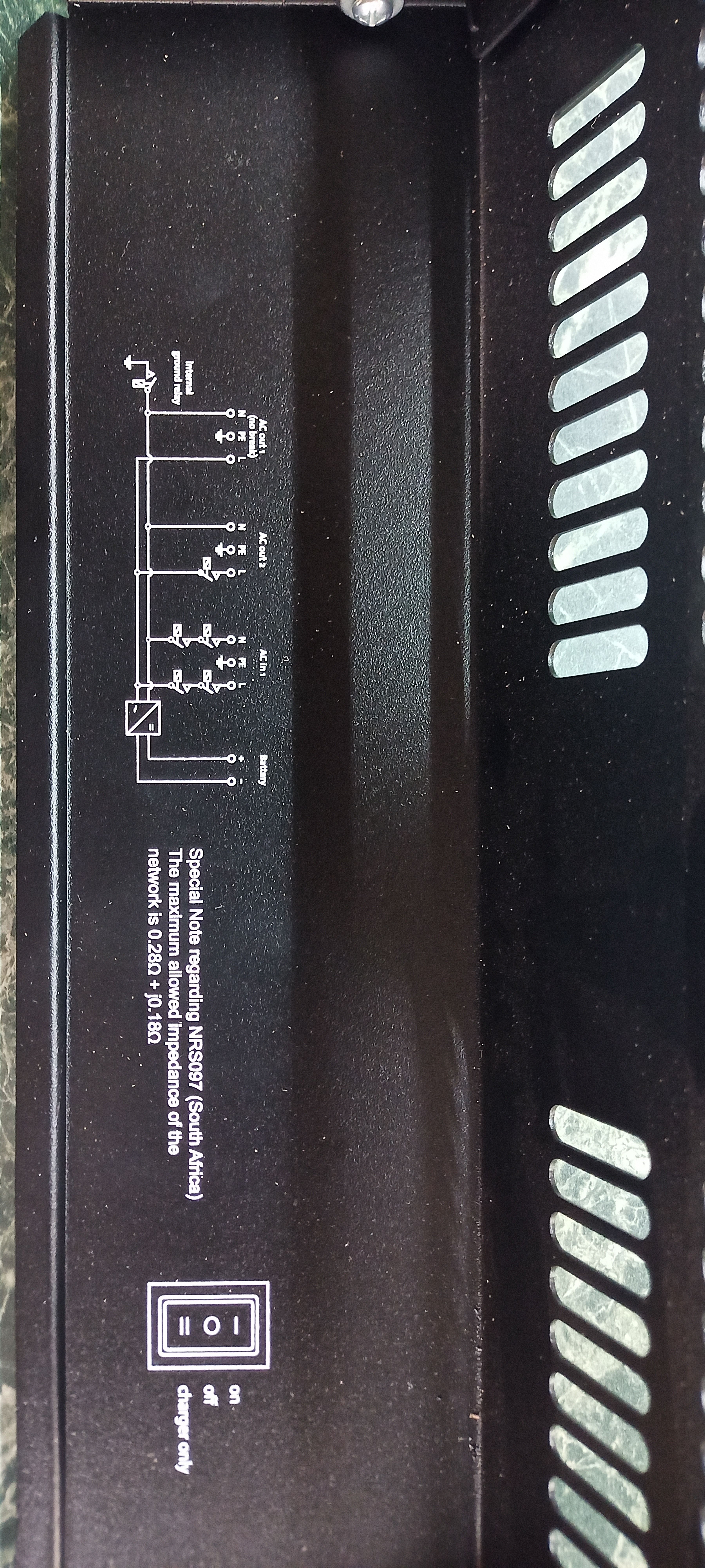
The drawing inside the unit only shows AC1 out disconnect and Ground to neutral lift consistent with the wording of the instruction.

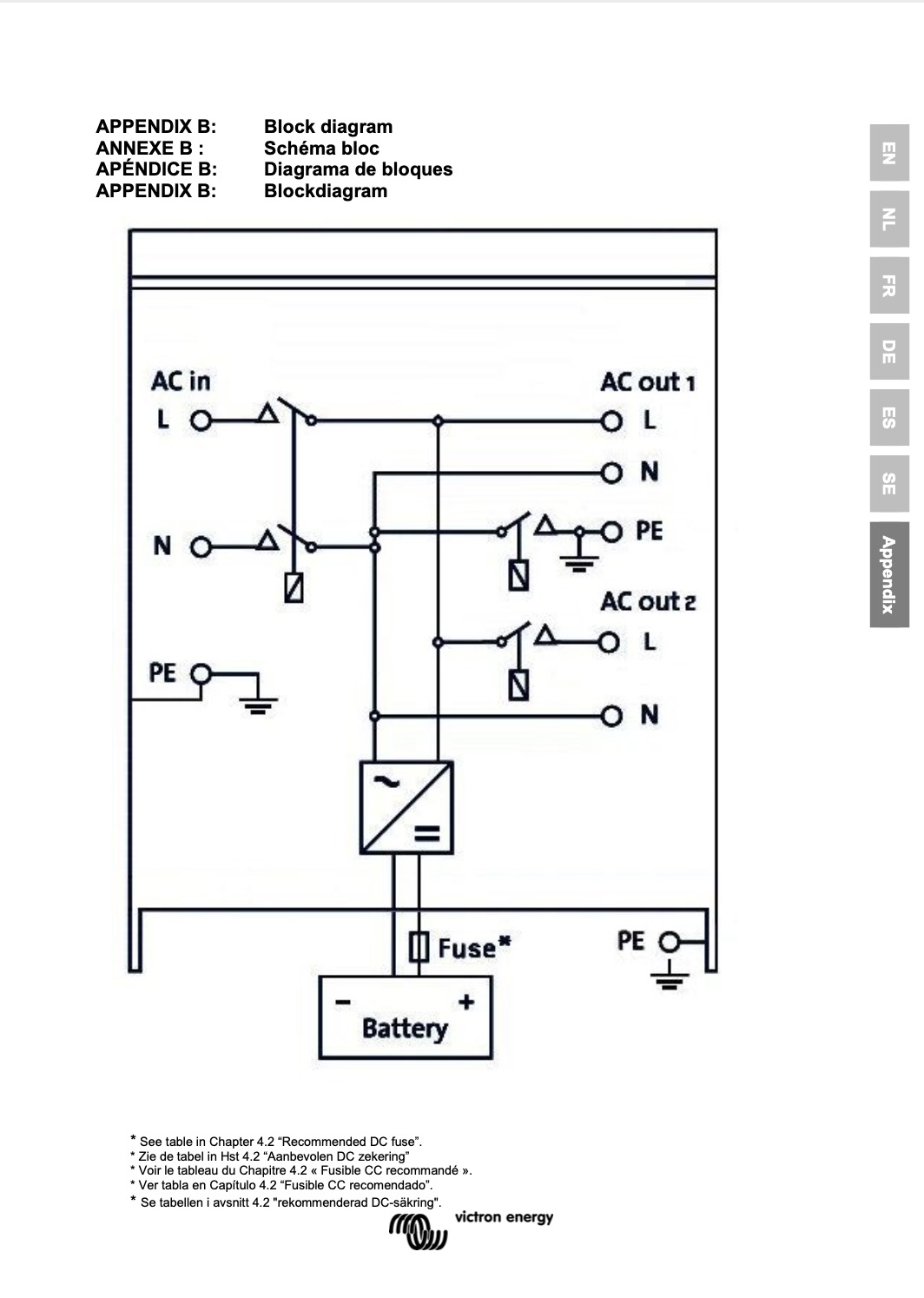
However, on the same model manual, I found a diagram showing ACout 2 disconnecting L and Pe

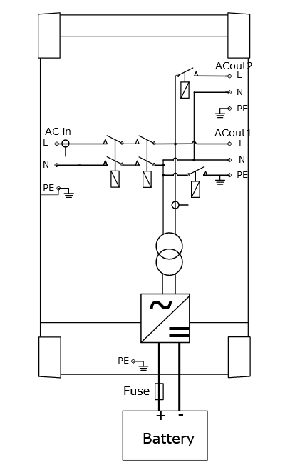
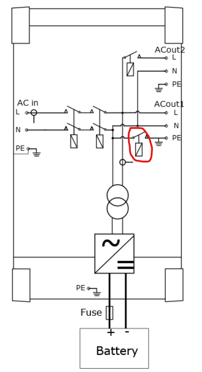
and in another diagram forwarded to me by a member yet another arrangement with AC1 out Pe ground lift.

What I need is to know if all Pes are bonded to the chassis at all times or if there are situations where one or more gets disconnected from the others.
BTW, if someone is kind enough to explain why Victrons call Pe that way I would be interested.

