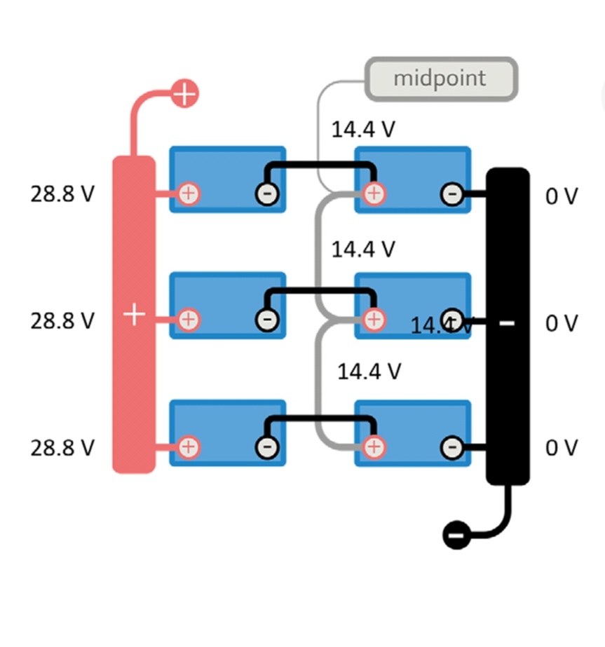
In my 48V ESS system, I use 2 groups of 2 24V batteries connected in series, in parallel. I have provided a Smart Shunt in each group to monitor the SOC and the midpoint deviation. The batteries have their own battery management system integrated and communicate via minor voltage and current differences.
Unfortunately, I can only specify one device in the battery monitor. As a result, the battery's charging capacity is only half of what it should be.
How can I configure a virtual battery monitor that displays the sum of both currents and the mean value of the SOC and voltages as Battrie SOC and voltage?
- Home
- Anonymous
- Sign in
- Create
- Spaces
- Grafana
- Node-Red
- Unsupported topics
- Questions & Answers
- Modifications
- Communauté francophone
- Deutschsprachiger Bereich
- Preguntas en Español
- Explore
- Topics
- Questions
- Ideas
- Articles
- Badges
question
How can I configure 2 Smart Shunts for use as a battery monitor?
Hi @Thomas Manthey ,
I'm not aware of anything out of the box other than getting another smart shunt to monitor the whole pack (easiest in my opinion unless you're good at python/know venus os).
If you did want to go the virtual battery monitor route I imagine it's possible using a custom drive to make a Virtual battery monitor and then populate the values of that virtual device by reading the dbus addresses of the existing two battery monitors and storing them into the virtual battery dbus.
velib_python/dbusdummyservice.py at master · victronenergy/velib_python · GitHub
And edit the service name to com.victronenergy.battery.tty01
Then look at the various dbus addresses noted here:
dbus · victronenergy/venus Wiki · GitHub
This might be a good starting point if you want to go down that route.
I have experience creating a virtual device. The dbuysdummy.py does the bulk/all of the heavy lifting in setting up the virtual device. However I've only ever used it for virtual tank sensors so to populated the data via dbus, I've instead done that via MQTT. Whereas I imagine you'd just read and write directly from the dbus rather than going via mqtt. I've not had experience is reading/writing to dbus I think there are functions setup in the github links above but I'm not clued up on them enough to give any further detail.
You may also be able to populate said virtual battery monitor using node red if that's easier than reading/writing dbus via python.
Personally I don't like the idea of adding another system (Node red) as just feels like another potential point of failure, especially when it's more important data like battery information. So if you're going the virtual battery monitor route i'd personally stick with python. (Probably also doable in C++ if you prefer but a lot of the github info I've seen is python)
You may also get some more success moving this to modifications section if you're writing a custom python driver for venus os. (Let me know if you go this route, Id be interested to see how the custom driver comes along).
EDIT: I've assumed in the above that there's no safety implications of using the average of the two battery monitors to populate the virtual monitor. This may be an unsafe assumption on my part. Make sure you're confident that it's safe to use average. ie BMS have applicable protections for example in the event that one pack voltage spikes high and the other spikes low => nice average voltage but in reality both packs are unsafe.
Hi @matt1309, thank you for your quick reply. Normally I program in C, C++, Assembler and Pascal. Why not Python as well? ;-)
If you have experience with programming device drivers under Linux, I would be very interested in this knowledge. I'll have a look at the sources in your answer first.
But now I have to mount the solar panels on the roof again while the weather is still good.
Hi, @matt1309 I have already done a lot of hardware-related programming for the Raspberry, but unfortunately not yet under VenusOS.
So I guess I have no choice but to learn Python.
A smart shunt by design is meant to measure one bank, that is the entire capcity and amps going to and from it. Also the monitoring system is set up for one master shunt.
The shunt already measures midpoint as a feature, so you don't actually need two shunts for that.
Hi, @Alexandra,I hope it doesn't sound rude if I ask you to read my original description again carefully. I have connected 2x2 24V batteries to 2x48 V in parallel. So I also have 2 different midpoints and 2 currents to monitor.
Not at all @Thomas Manthey
I know the picture below is for 24v and a battery balancer (which monitors and corrects midpoint deviations), but will work for 48v with a shunt as well for midpoint monitoring.

There have been a few fellers on here that have created a virtual battery driver that can enable you to select the virtual driver as the main battery for the Venus device, and select which devices you want to report to the virtual driver to feed the aggregated information. Do a forum search for virtual battery driver or battery aggregator.
I did the search as you described. Unfortunately, I could not find a post that addressed my problem. Could you please add a link to the post you are talking about?
https://github.com/arrow1800/Victron-VirtualBattery
Related Resources
SmartShunt Installation Manual
SmartShunt Quick Installation Guide
ESS design and installation manual
Additional resources still need to be added for this topic
Did You Know - How to create a battery profile for non-Victron batteries?
question details
75 People are following this question.
