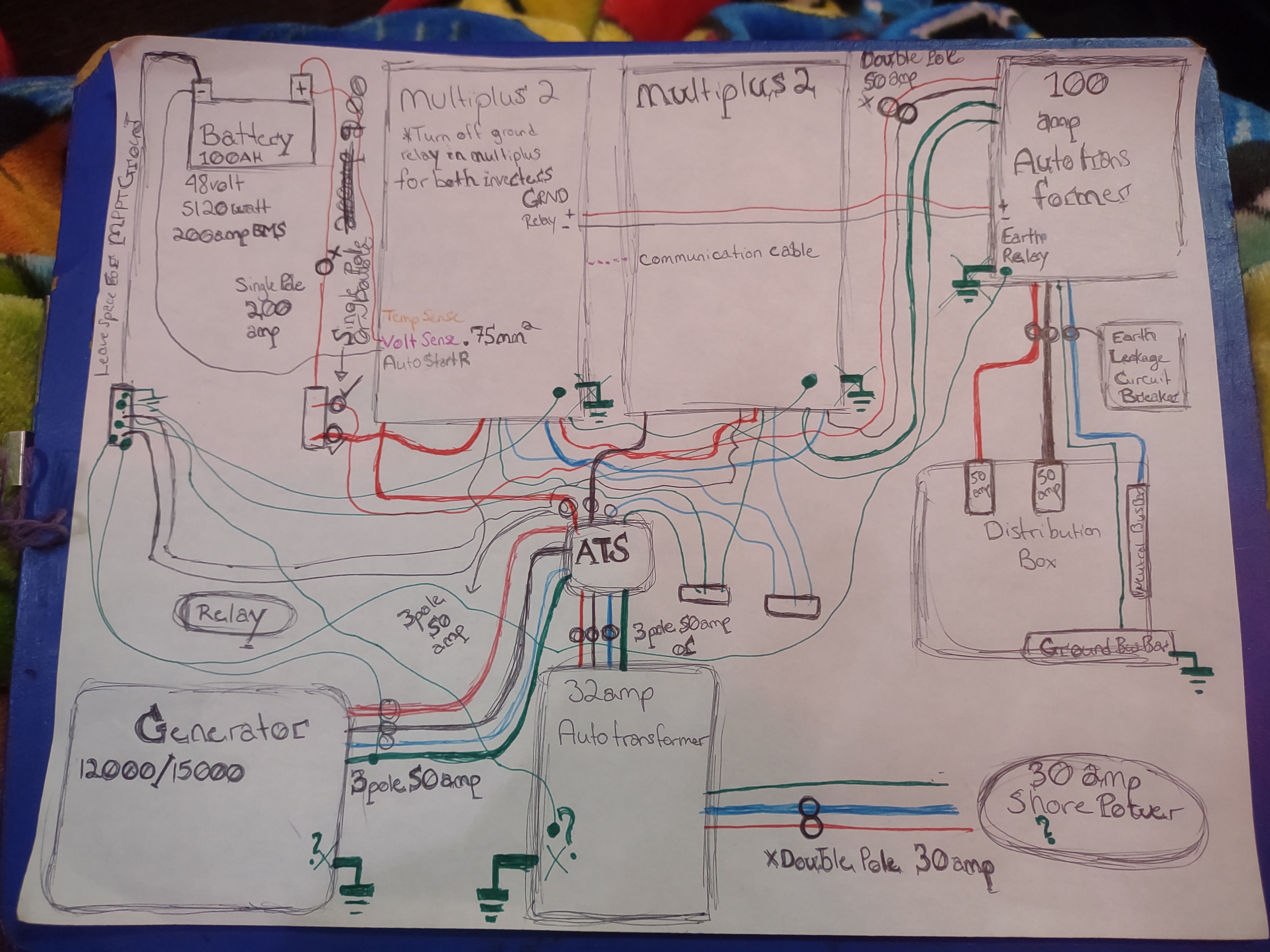
Link to my hand drawn wiring diagram:

This is not a perfect or complete diagram, I am still figuring some things out like breaker placement, the auto start relay, and the temperature sensor. However it should be enough information to be able to answer my question. The busbars are those small unlabeled rectangles, the circles are where I have been debating if breakers should go. And I have crossed out some things.
I am using two Multiplus 2 units 48/5000, I am connecting a DC battery bank (1 battery at first that will be expanded to 4). I will be using the Multipluses in split phase. I will have generator hooked up to an automatic transfer switch, and a 30 amp shore power cord will run through a 32 amp autotransformer to be converted to split phase and the output of the autotransformer will also run into the automatic transfer switch. The output of the automatic transfer switch will go to the 2 Multiplus units (I have not at this time added a bypass switch but plan to, here). The multiplus units go to a 100amp autotranformer that will be used for balancing. The output of that autotransformer will go to my distribution panel.
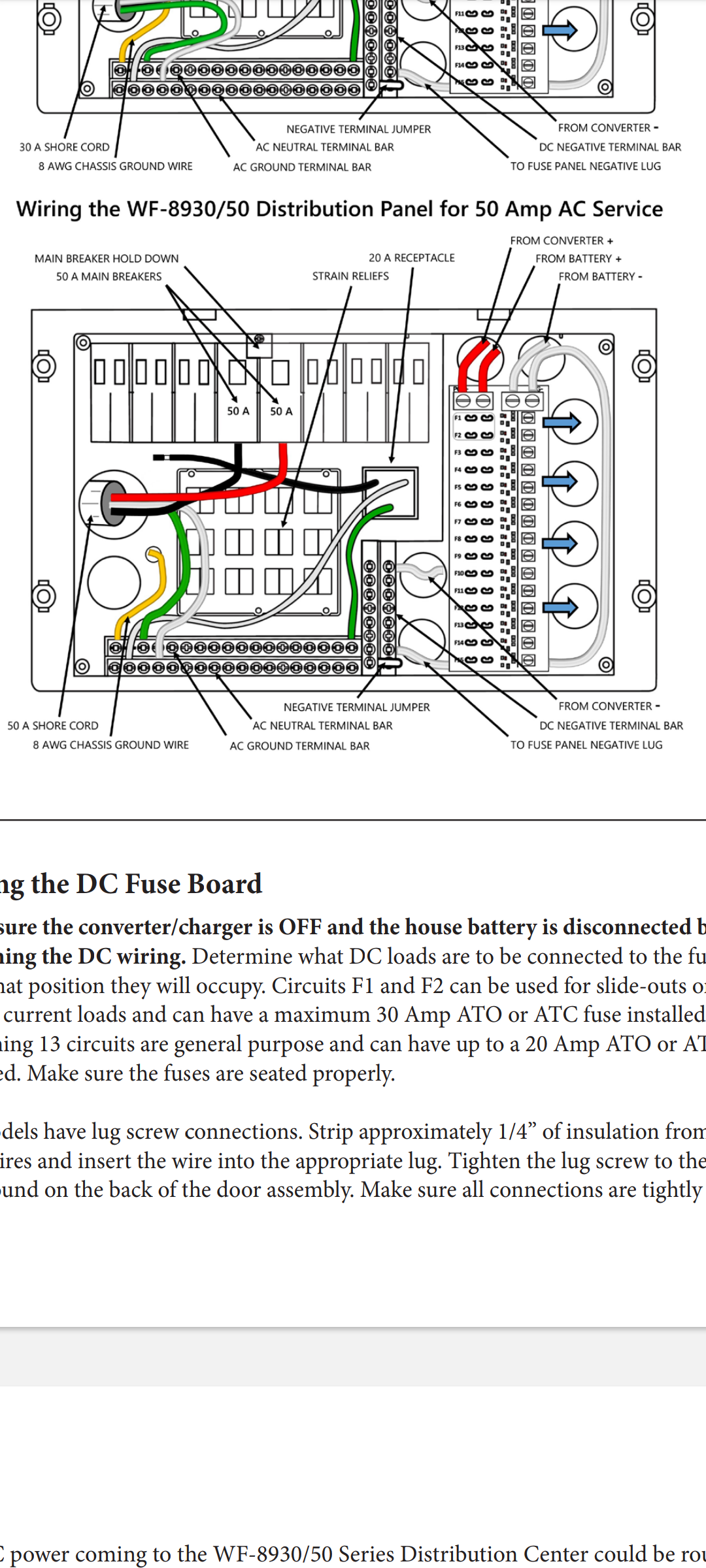
Wiring Diagram of Distribution Box from manual:

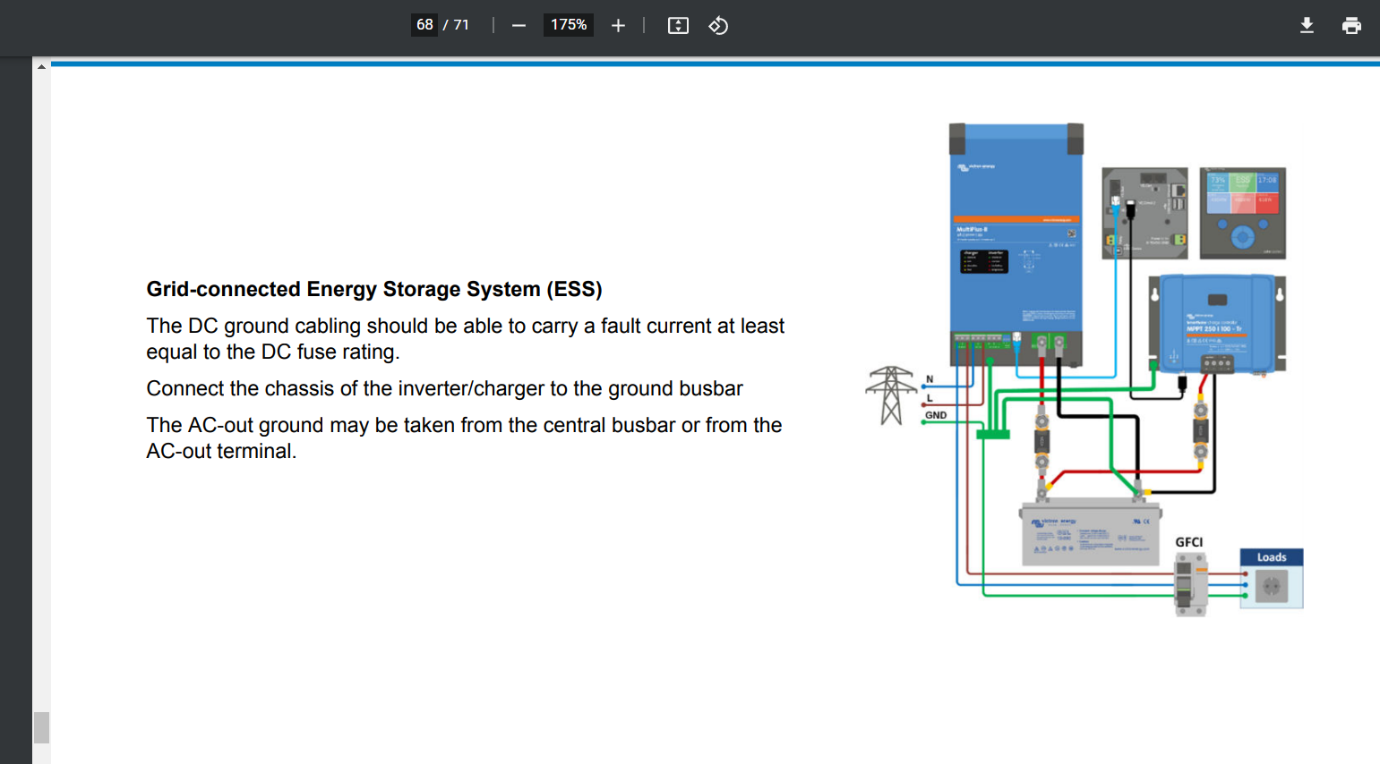
Ground Diagrams From Wiring Unlimited:


My question is: Where do I connect the main ground of the 32 amp autotransformer to? Is it okay to connect it to the negative DC busbar with everything else?
Does my main ground on my distribution box go directly to the RV chasis? Or does it need to go to the negative DC busbar with everything else?
Also, it looks like the 30 amp shore power needs a wire splitting off from the ground that goes to that same negative DC busbar, do I do that before the 30amp auto transformer or after it before the automatic transfer switch.
I have included all the diagrams I have been using as a wiring references.
I have included links to all the components of this system.
So all of the diagrams say that the inverter/chargers should be grounded to the central negative DC busbar. And it says that the autotransformer should be grounded there too – however in the diagrams where it says this the autotransformer is always after the inverter/chargers. The one I don’t know where to send the ground to is before the inverter/chargers. I do plan to charge the battery bank from the 30 amp shore power and to supplement loads from the battery bank when pulling from 30 amp shore. Don’t know if that makes a difference.
Also, the diagrams in Wiring Unlimited, show connecting a ground wire to the negative battery terminal and connecting that wire to a ground bus bar where all the grounds I was going to put directly on the negative busbar go to. And that bus bar actually goes to the main grounding point. Is this acceptable in my system? Can I do this instead? It just seems like a cleaner wiring design. I though that electrically speaking its the exact same setup as grounding at the negative bus bar, but don’t want to misunderstand something. This looks so much cleaner and I want to know if its okay to wire my system this way. See attached photos or Wiring Unlimited.
Stacked Inverter Balancing with Generator - Autotransformer
120 to 120/240 split phase
Products
Multiplus 2
https://www.victronenergy.com/inverters-chargers/multiplus-ii
Autotransformer
https://www.victronenergy.com/autotransformers/autotransformers
Generator
https://westinghouseoutdoorpower.com/products/wgen12000c-generator-with-co-sensor
Go Power Auto Transfer Switch
https://gopowersolar.com/products/50-amp-transfer-switch/
EG4 Battery
https://signaturesolar.com/eg4-wp-lithium-battery-48v-100ah
Distribution Box
https://wfcoelectronics.com/product/wf-893050-distribution-panel-series/
