question

chrisriche avatar image
chrisriche asked

Help with pre-charging issue on two Quattro 5000VA inverters

May 25, 2023 update:

Thanks for the helpful advice, everyone. As an update, here's what I've learned, and I think we can consider this question closed:

1. Multiple inverters in parallel apparently put greater stress on battery pre-charge circuits than the same combined size as just one inverter (i.e., 2 x 5000KVa vs. 1 x 10000KVa).

2. It seems worth trying other battery brands, such as EG4, to see if they have better pre-charge circuits than the SOKs. Despite now having 4 x 100Ah 48v SOKs connected, I am still occasionally getting an alarm when trying to pre-charge two paralleled inverters. Importantly, SOK support hasn't been super helpful in the processes. They are unwilling to talk to me directly, don't have a developed community I can fall back on, provided what feels like cut-and-paste info to the distributor I work with, and showed little real interest, IMO, in if that reply actually worked and if the problem was addressed.

3. This Victron community has been very helpful. I appreciate the level of response, the thoughtful questions, and the helpful insight. Thank you all.

--------------------------------------------------------------------


Original post:


Context:

Last year I built a power station for our camp at Burning Man. At its core, it has two Quattro 5000VA inverter chargers wired in parallel with a large bank of SOK 48v 100Ah batteries recharged from some solar shade structures I built. The system worked fine at burning man and at the end of the season. The only change after that was to remove the batteries to protect against freezing. They are fully charged. See the system picture attached for context if helpful.

Problem:

Today, six months later, when powering up the system, each battery's BMS goes to alarm mode, which I'm assuming is because the inverter capacitors are drained.

What I've tried:

With no luck, I tried pre-charging them using a 50w 30 Ohm resistor between the negative battery terminal and the wire leading to the Lynx. After some research, I then decided to try a 200w 50 Ohm resistor setup. No luck. I waited until the voltage stabilized at ~52.4v on the MPPT display each time and then some, with no success. For this startup test, I only used two of the SOKs, but I imagine that would have no impact vs. using more.

A few pieces of additional perspective:

1. If I remove the power cables from the Lynx to the Inverters, the rest of the system powers up and works just fine.

2. I looked inside the Quattros and inside the Lnyx for possible shorts, but don't see any.

3. I removed the remote pass-throughs for the Phoenix, two 48-12v DC-DC converters and unplugged the Cerbo to minimize anything stealing the limited power from the Quattros. The MPPT is still plugged in (I'm using the display to monitor the system voltage), but at 20mA, that shouldn't have any impact. Nothing changed.

4. I tried only having one Quattro connected with no luck

5. Waiting longer for the inverters to pre-charge (I tried for up to a minute) seems to have no impact.

6. I've tried different resistors with no change in results, so I assume it isn't a b broken resistor issue.

Request:

Help. :) What am I doing wrong? Thanks!img-4445.jpg
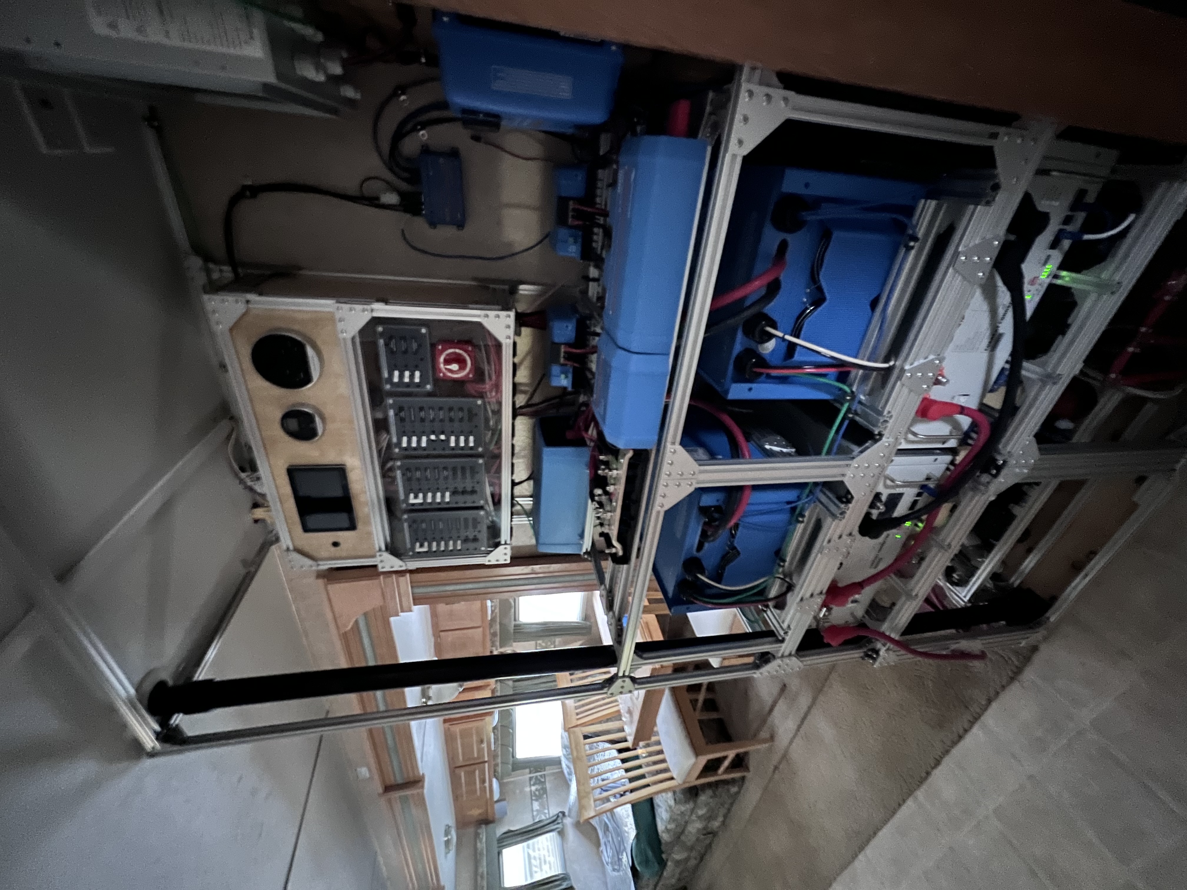
MultiPlus Quattro Inverter Charger
img-4445.jpg (2.6 MiB)
2 |3000

Up to 8 attachments (including images) can be used with a maximum of 190.8 MiB each and 286.6 MiB total.

4 Answers
mvas avatar image
mvas answered ·

So, exactly what happens after the resistor pre-charges the Quatro? Put a volt meter on the Bat (+) and Bat (-) input terminals on the Quatro. Do you see the 52 volts there? The 30 ohm resistor should be fine.

Are you 100% positive that the battery polarity is correct?

1 comment
2 |3000

Up to 8 attachments (including images) can be used with a maximum of 190.8 MiB each and 286.6 MiB total.

chrisriche avatar image chrisriche commented ·

Battery polarity is definitely fine. The mppt display was showing good volts, but I’ll test again at the inverter terminals. Battery bms’ go right into alarm once everything is connected, even after the pre charge, but are happy as clams without the Quattro, even when I use the phoenix inverter. I’m definitely at a loss on this one so any thoughts are greatly appreciated.

0 Likes 0 ·
Michelle Konzack avatar image
Michelle Konzack answered ·

Battery bms’ go right into alarm once everything is connected, even after the pre charge,

This sounds mor like a Battery issue, that it does not have the capacity to hold the voltage up to start the Inverters.


After the 6 month period, how long did you charge the batteries with the MPPT?


And

The only change after that was to remove the batteries to protect against freezing. They are fully charged.

and are you sure with this?

1 comment
2 |3000

Up to 8 attachments (including images) can be used with a maximum of 190.8 MiB each and 286.6 MiB total.

chrisriche avatar image chrisriche commented ·
I'm starting to think it might be the batteries as well. Over the winter, they were kept indoors and charged with a 48v charger. I'm just using the MPPT to read the voltage since it is connected to the Lynx Power In. I didn't use it to charge the batteries. On the display for the SOKs, and on the Cerbo, the SOKs are showing a 99% charge and are able to power the Phoenix 1200W Inverter and the rest of the system. Very perplexing.


I'm going to bring in a 3rd SOK and try to connect it by itself after I do the pre-charge process again (in case there is some hidden BMS issue now).

0 Likes 0 ·
Matthias Lange - DE avatar image
Matthias Lange - DE answered ·

I only used two of the SOKs, but I imagine that would have no impact vs. using more.

If you have more batteries, connect them all.
The more batteries you have the less inrush current has each battery to handle.

4 comments
2 |3000

Up to 8 attachments (including images) can be used with a maximum of 190.8 MiB each and 286.6 MiB total.

chrisriche avatar image chrisriche commented ·
Good thought. It definitely seems worth a try at this point. Thanks.


This idea does raise a question. How many amps does an already pre-charged Quattro that isn't on actually need on system startup? I would have thought almost nothing, or at least well less than 100 amps.


Regardless, I really appreciate everyone's feedback/ideas and am definitely going to give them all a try today. Thanks!

0 Likes 0 ·
chrisriche avatar image chrisriche commented ·

@Matthias Lange - DE , it looks like your thought may be the right one.


What I did:

I added a third SOK, disconnected everything besides the batteries, Lynx and Inverters, closed all circuits with the BMS off, then turned on one of the SOK BMSes.


What happened:

The system "just barely" started. I say "just barely" because one of the batteries still went into alarm mode (and subsequently reset). As additional perspective, if I have the MPPT, for example, also connected to the Lynx on startup, then all three batteries go into alarm mode.

Importantly, recall that the MPPT is fine in and of itself. I say this since, without the inverters connected, everything, including the MPPT, starts up fine.


Possible conclusion:

One potential takeaway is that each Victron needs something over 225 amps to power up. I say this since 450 amps (3 batteries x 150a, which is where I think the SOK's SPC kicks in) could barely start up two inverters. Yes, I hurt my back earlier this week and have no desire to haul a fourth 45-kilo battery to the RV to try four batteries at once...


However, this seems odd. Why would this be necessary with a pre-charge circuit built in? Also, when I added a load to the inverters from a heat gun (@ ~500w), the right inverter was making a noise like a fan was starting up, but not the left inverter. I don't recall that before

Thoughts? Thanks!

0 Likes 0 ·
snoobler avatar image snoobler chrisriche commented ·

The pre-charge circuit sounds like it's malfunctioning.

Precharge method:

  1. Disconnect primary (+)
  2. Everything but inverters removed from circuit.
  3. All batteries on.
  4. Insert resistor between (+) terminal and (+) cable.
  5. Hold until battery voltage is measured at quattro terminals.
  6. Immediately remove resistor and make contact between cable and terminal.
  7. Secure cable.
  8. Confirm battery voltage is present at Quattro terminals.
  9. Power on each Quattro.
  10. Reconnect all other devices to DC bus.

Did you conduct it analogous to the above.

Rather than a high Ω resistor, a #2 pencil with both ends exposed is about 6Ω, and it can easily handle the current/power.

Concerning the 500W heat gun, if your inverters are configured for 120/240VAC split phase, then only one inverter powers each leg, so if you're on L1 with a 120VAC heat gun, only the L1 inverter is providing 120VAC to that leg and powering the heat gun. The other is just sitting there synchronized 180° out of phase from L1 burning ~30W of idle power. If your inverters are in parallel for 10kW of 120V, you may have an issue with wiring that results in uneven draw from each inverter.


0 Likes 0 ·
chrisriche avatar image chrisriche snoobler commented ·

Hello @snoobler, thanks for the reply. To your points:

I have been following that process but using the negative, not the positive, terminals. I'll try that for completeness. Thanks.

To your other thoughts: I'm running the two inverters in parallel, so basically, a giant 10KVa inverter @ 120v. Each inverter pulls from the same Lynx Distributor using equal size and length wires. I'm hoping they are not pulling unevenly, but I'll look more into that since that seems bad if it is happening. If you have any ideas on how to check that, I would love to hear them. I'm definitely at the edge of my knowledge here.

I did hear back yesterday from Current Connected (SOK batteries) via a distributor I use, and they said:

  1. The pre-charge circuit should be able to handle up to about 10Kw, but not two smaller inverters totaling that size in parallel, which mine are. So I can see the need for two batteries (but I need three for some reason, and even then, it barely works, so who knows).
  2. The Ohm level on the resistor I'm using is too high (so much for Google...lol). Consistent with your point, they recommend 10w 10 Ohm as being enough, but I will also have to try the pencil idea. :) I ordered a lower Ohm resistor, which should be here today.

It's a shame. I have liked SOK batteries, and their price is reasonable. Still, I'm looking to build much larger power stations (40KVa) for use at Burning Man, and while I'm comfortable using 4x10KVa Quattros, for example, I don't see how I can scale using SOK batteries if I am not confident in their pre-charge circuits. This is compounded since they appear to have no interest in talking directly with me since I'm not a dealer of theirs yet, and, unlike Victron, they don't have a community like this to fall back on.

Thanks for your and everyone's help. I really appreciate it.

0 Likes 0 ·
snoobler avatar image
snoobler answered ·

Are these the SOK server rack batteries? If so, they're supposed to have a pre-charge circuit built in.

Power-Up procedure (using automatic pre-charge)

Whenever working with electrical systems, proper PPE must be worn, including safety glasses, insulating gloves, closed toe-shoes, etc. otherwise personal injury may occur if your system is miswired.

  1. Thorougly inspect the system for any miswiring (loose connections, short circuits, reverse polarity) and correct any issues before proceeding
  2. Confirm all DC circuit breakers and switches in the system are in the “OFF” (open) position – Typically they should already be off during the wiring process.
  3. Ensure the BMS(s) in all batteries have been de-activated – this means none of the LED lights on the front panel are illuminated.
    • If the BMS is active, you can turn it off by pressing and holding the “RST” button with a small screwdriver or similar object for approximately 3 seconds, releasing the button when the SOC% lights begin to flash. A few seconds after releasing, all lights and the display display will turn off, which indicates the battery has shut down.
  4. Turn on (close) all DC breakers and switches in the battery system. This includes turning on the DC breaker located on the front panel of all the SK48v100 unit(s).
  5. Briefly press the “RST” button of any battery. This will immediately engage the pre-charge circuit of that battery, which will charge any capacitors in the system. After pre-charging is complete, the pre-charge circuit will be automatically disengaged and the main power circuit will be enabled.
  6. If additional batteries in the system have not turned on automatically when the first battery was turned on, turn them on now by briefly pressing their “RST” button.
  7. If none of the red “ALM” lights have illuminated, the system is now ready for use.
  8. If however, you follow the process and it triggers the “ALM” light, this means you have triggered short-circuit protection. You will need to turn off the DC breaker on the battery, wait 60 seconds for the protection to automatically clear, power down the BMS as mentioned in step 2, and then repeat this process. If after two tries you continue to trigger short-circuit protection, your inverter is beyond the circuit’s capability and must be manually pre-charged as described in the next section.


2 comments
2 |3000

Up to 8 attachments (including images) can be used with a maximum of 190.8 MiB each and 286.6 MiB total.

chrisriche avatar image chrisriche commented ·
I went through that, but I will try again. The first time I tried that, I thought maybe it wasn't working because I have two Victrons connected, and they were overwhelming the pre-charge circuit in the BMS. However, I've tried so many things since then perhaps I did those steps incorrectly. This stuff usually seems to come down to "operator error."


Thanks for the reminder. I'll try this before lugging more 45 Kilo batteries into that RV. :)
0 Likes 0 ·
Show more comments