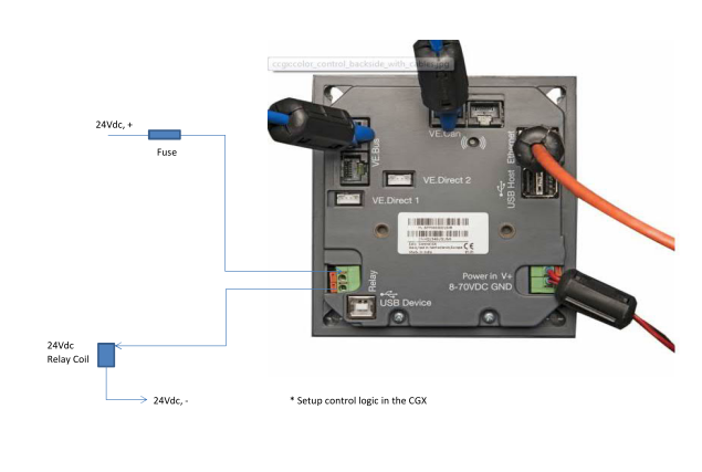
I would like to wire a remote relay to either my battery monitor (BMV 702) or Color Control GX. Neither product's manuals show how to physically wire the BMV/ Color Control to the relay. Please could someone share a schematic with me. Thanks.
- Home
- Anonymous
- Sign in
- Create
- Spaces
- Grafana
- Node-Red
- Unsupported topics
- Questions & Answers
- Modifications
- Communauté francophone
- Deutschsprachiger Bereich
- Preguntas en Español
- Explore
- Topics
- Questions
- Ideas
- Articles
- Badges
question
Hello,
I have a question about this topic.
Why is there two points on the BMV702 and two points on the CCGX too. Is it two distinct relays for each device, or does a single relay need two wires?
Moreover, no need of a fuse for the relays?
If it is «simply» a switch, what voltage/current can go through??
Thank you,
@drumond, per the technical specifications on page 39 of the manual, the relay can handle 1A up to 30vDC and 0.2A up to 70vDC, or 1A up to 50vAC.
...and yes, you should of course fuse your wires as you would any wiring.
Thank you but I still can't manage what for to wires are necessary with one single relay. Would it have been simpler with one wire, 0V = relay off / 9V and above = relay on.
I don't understand how your relays work. Maybe I am more stupid than I thought.
@drumond, it's not a two-wire relay, the 702 has two ports on the back, one for in, one for out. You feed a 12v POS (or 24v, whatever your native voltage is) IN to one port, and a wire OUT to the remote switch/whatever of an external device that you want controlled by the BMV, then program the BMV when to close the relay, thus connecting the two wires together (ie, send a 12v signal to an external device).
On the 712, there are 3 ports: one marked COM, into which your 12v POS wire goes, and then there is a NC and a NO port... NC is "normally closed" and NO is "normally open" and you can program when/if each side opens and closes.
It's worth noting that this is NOT a common automotive-style relay (which will usually have a minimum of 4-5 wires to control one device, and be capable of much higher current) but it is instead a simple on/off relay that can be used to remotely switch an external relay or other device based on the parameters that you set within the BMV.
Thank you.
I would like to have the Cyrix Li Ct open when the Lifepo4 is above 13.8V (or any chosen voltage).
Could I do the wiring as following:
One wire that goes from the Ve Bus BMS Charge disconnect port to one of the two relay ports on the back of the BMV702 (I suspect no matter which one of the two ports).
Another wire that goes from the other port of the BMV702 relay to the Charge disconnect port of the Cyrix Li Ct.
Should it work?
Regards.
Hi @Flip-Flops,
Below is a rough schematic of how it can be wired. Please note the voltage and current limits provided on the CGX datasheet.
The logic to control the CGX relay contact can be setup via the CGX.

External relay circuit not shown.
Best Regards
Riaan
Related Resources
question details
12 People are following this question.
