How can I connect the relay terminal of the BMV-712 battery monitor with a BP-100 battery protect? I want to disconnect the battery in case the capacity of the battery has reach a defined percentage. I only can programm the cut off voltage off the BP-100, but I want to use the capacity information from the BMV-712.
- Home
- Anonymous
- Sign in
- Create
- Spaces
- Grafana
- Node-Red
- Unsupported topics
- Questions & Answers
- Modifications
- Communauté francophone
- Deutschsprachiger Bereich
- Preguntas en Español
- Explore
- Topics
- Questions
- Ideas
- Articles
- Badges
question
Connecting Battery Monitor BMV-712 with Battery Protect BP-100
Greetings
I am also interested in connecting my 712 to my 65a SBP via the NC and COM to set a HIGH V. cutoff. I have made connections but not sure where to make the settings in the 712 or whether there are any separate settings in the 712 menu to make. I have done a simple over voltage test from my Smart 30/100 MPPT to the SBP but no cutoff occurred.
Can you please help?
Ty
Krystof
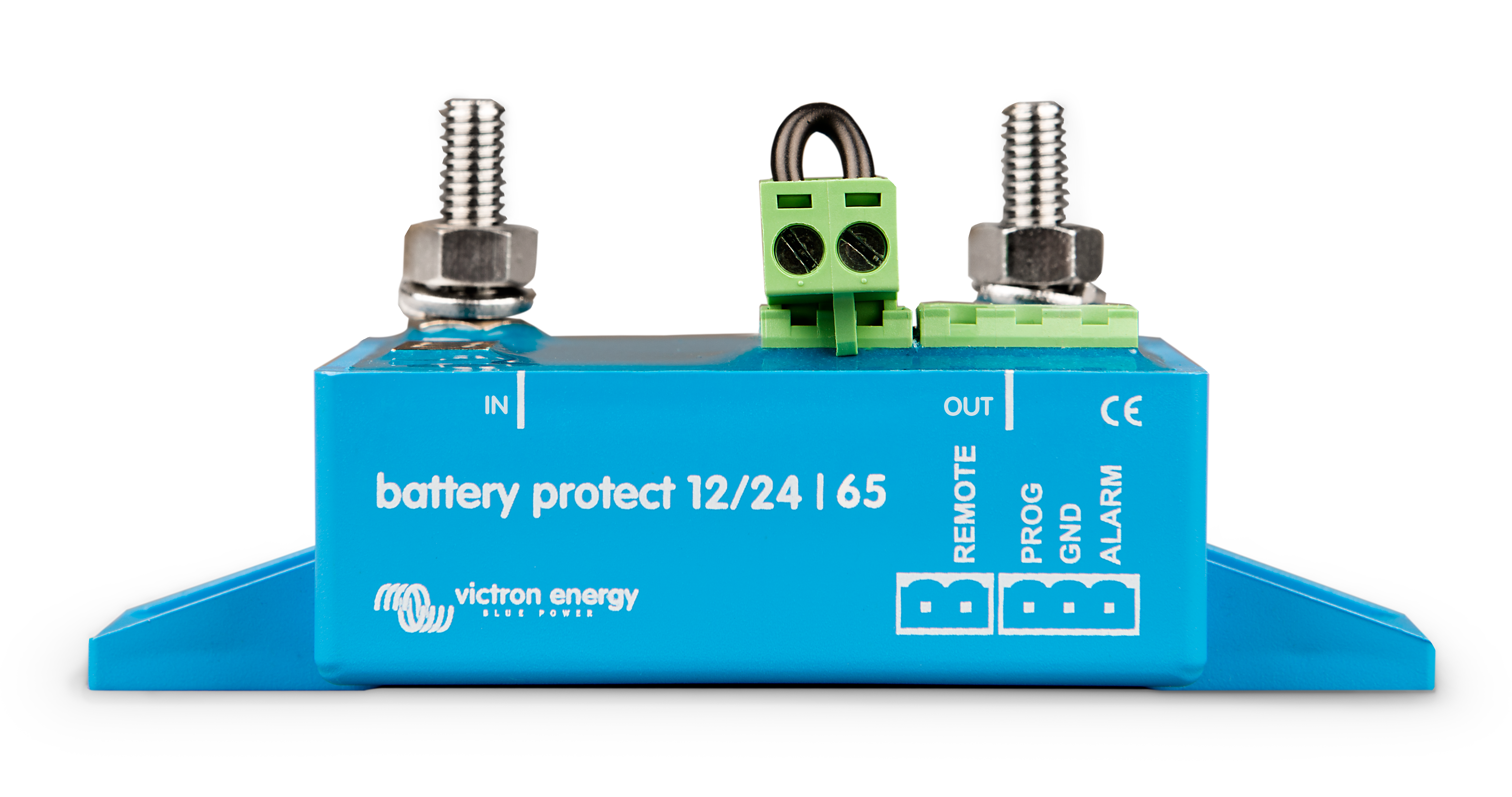
The battery protect has a High+ and - Connection where the loop is connected.
It it very simple to use. Take the wires out the loop terminal on the battery protect
and run a pair of wires to the back of the BMV-712. Connect one wire to the common
terminal and one to the normally closed.
I understand the BMV uses a bi-stable relay and is a clean pair. This way you can set the
relay to change over when the battery gets low and all your loads will be isolated stopping
any further discharge. In other words you are just using the relay on the battery protect to
switch the main power switch output.
If you are not sure you can draw out a circuit diagram of how you have the system wired
and myself or another member will be able to give you further advice.
I hope that is of help.
Stuart.
Hello, I am also interested in connecting my 712 to my 65a SBP via the NC and COM to set a HIGH V. cutoff. I have made connections but not sure where to make the settings in the 712 or whether there are any separate settings in the 712 menu to make. I have done a simple over voltage test from my Smart 30/100 MPPT to the SBP but no cutoff occurred.
Can you please help?
Ty
Krystof
Is there any more feedback on this question. I ask because victron support suggested that I talk to a major distributor in the US about a similar question and I got a different answer. This is what I asked:
I'm looking for a solution that will disable solar-only charging to a 24 volt lithium ion battery at low temperature. I am currently using a Victron BMV-712 to accurately monitor the battery temperature. Can I use the relay on the BMV-712 display monitor to directly manage a Victron BP220 to cut-off charging from the solar panels?
Here's the answer I got:
Yes you can do this easily with a BatteryProtect. The BMV has a relay terminal at the back and you program it to be on or off depending on temperature conditions.
Supply 12 volts to the COM terminal and the NO (normally open) and NC (normally closed) terminals will be ON (normally closed) and OFF (normally open). The conditions of the NO and NC terminals reverses when the alarm condition is met. Take the output of the NC terminal to the Remote connection of a BatteryProtect and then program it for PROGRAM C (lithium) The BatteryProtect will be ON when its remote terminal is +12 volts which will be when there is no alarm.
The BatteryProtect is a one way device has an IN and an OUT terminal for power. In this case solar is the IN and the battery connection is the OUT
This seems to conflict with the answer above and I have been unable (or unwilling due to the conflict) to get this working. Any additional information would be much appreciated.
Reviving this thread. I am trying to use the BMV-712 to open the relay on a BP-65 to control the output from a PVM controller when battery temp is low. I have the BMV NC terminal connected to the BP Remote terminal. I can trigger the relay on the BMV with a low temp trigger but nothing seems to happen on the BP. The BP does open/close with the loop jumper.
Hello and welcome to the forum.
Could you possibly post a screenshot of the relay setup screen please, a picture of the setup will also help. I have looked through the BMV-712 relay option screen and I can't see a temperature option.
A basic wiring diagram would be a huge help to.
Stuart.
@Stuart Thanks for replying.
The BP in question is outside of the dotted line (Normally Closed) on the attached PDF. Ignore the other BP. I have the BP programmed for Lithium. I have also tried it in Relay mode. In order for temperature to show in the app it has to be enabled in the BMV setup. When I connect the remote wires from the BMV NC to the BP remote terminal the BP relay closes as expected. It was 72F yesterday so I set the relay to trigger below 80F. I can hear the BMV relay switch but nothing seems to happen on the BP. I have everything set so the BP is NC but should change to Open at the set point. I can add app screenshots later.
Hello Again.
When you remove the link there are three ways to control the BP. With the link open no current will pass from the IN to the OUT. Closing the link is one method.
However you can control the BP in two other ways. 1- You can connect your common ground to the common on the BMV712 and then run a single wire from the NC on the BMV712 to the (L) terminal. When the ground is seen on that terminal the BP will allow current to flow.
Option two is to connect a wire from a permanent positive to the common terminal on the BMV712 then another single wire from the BMV712 NC terminal to the (H) terminal on the BP. When the BP detects a system positive it will allow current to flow.
Some things to remember....
You can only pass current from the IN terminal to the OUT terminal on the BP. Current will not flow in the opposite direction. Think of it as an electronic switching one way valve. If you wanted to control charge and discharge from your battery you will need two BP's. One for current into the battery and one for current out.
You can remove the link between the (H) and the (L) and connect a switch or the terminals from a relay to open and close the link. Or if you choose to use the system positive it must be connected to the (H) terminal on the BP. If you are using the ground it must be connected to the (L) terminal. You cannot use both at the same time. If you are using the (H) or the (L) terminals alone you must remove the link wire that comes fitted from the factory.
I hope this is of some help to you. Post back with your results as it will help others.
Stuart.
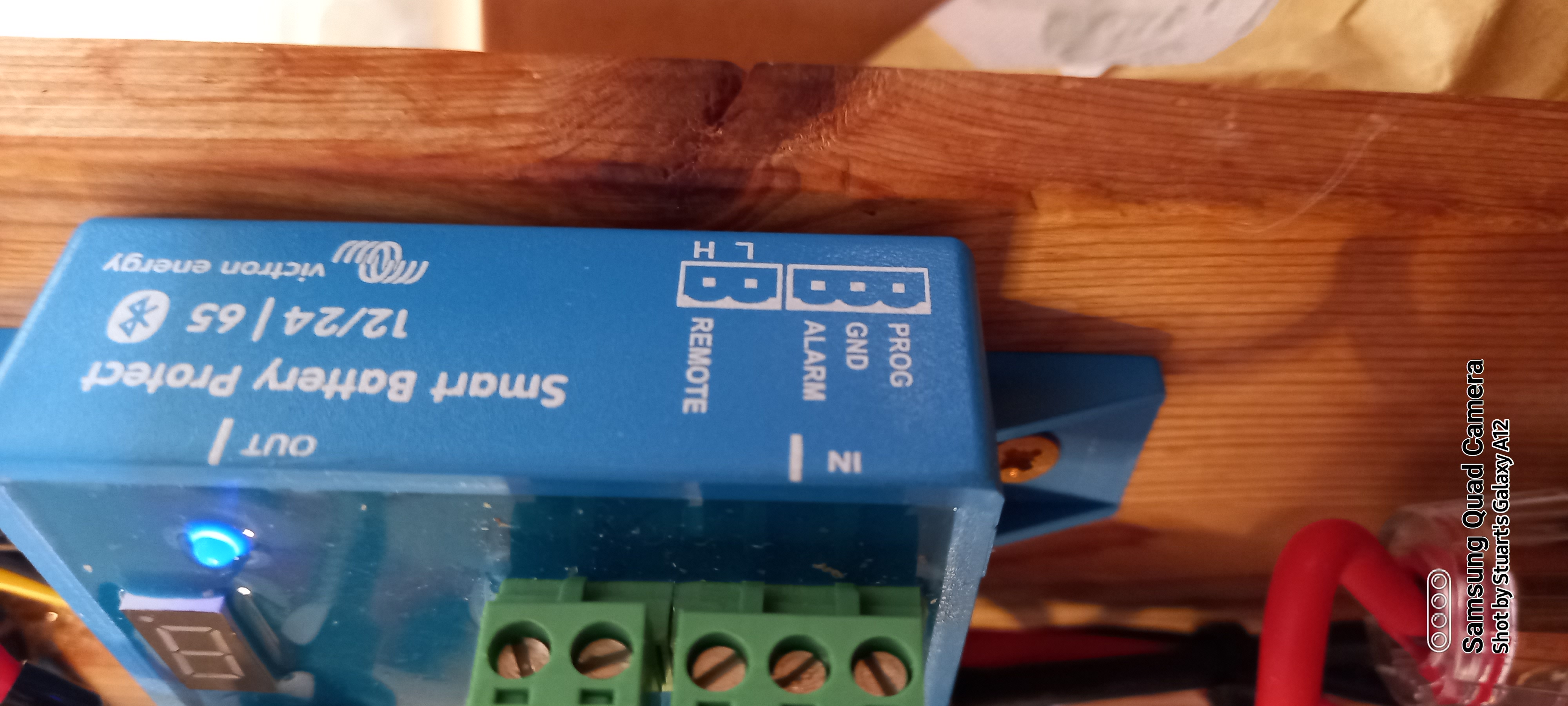
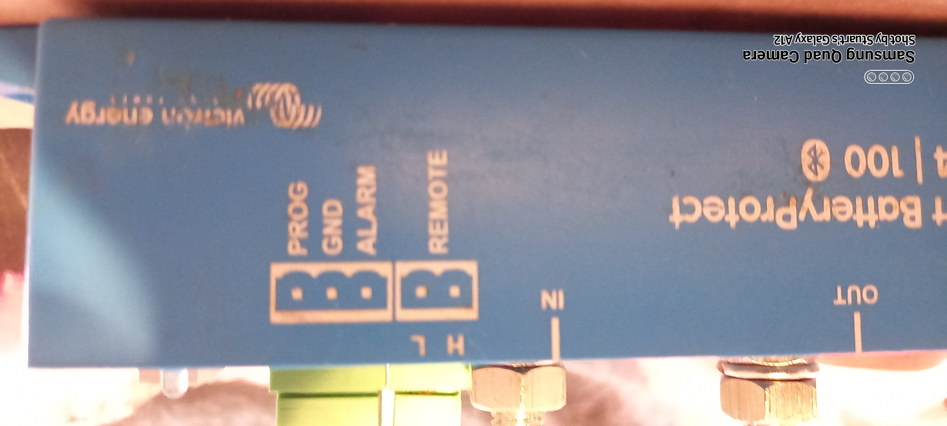
@Stuart Which are the H and L terminals? They are not labeled as such. The only terminal that is labeled is "Remote".
Hmm that's strange.
I have several BP modules including your model that I cannot find at the moment. I will have a look later today. Perhaps I have an earlier model.
I have attached a picture of one that is running next to me. I would imagine the terminals are the same but it may be an idea to dig into the manual. I am 99% sure that all the battery protect modules have this feature. You could try a ground connecting to be safe with a current limiting resistor to be safe.
I will post back when I find the other module that's the same model as yours.

Having another read of your first post I think your on the wrong pin. The prog pin is only for setup of the BMV in terms of its protection.
The remote loop is standard on most Victron kit and regardless of programing should stop the device in its tracks. Its basically a normaly closed stop loop. Your BMV should have the common and normally closed terminals connected in place of that link. You will find if you cut the link or pull out the block the BP will go open circuit.
Almost at my wits end. Without the correct labeling it is hard to determine if I am connecting things right. Isn't the BMV relay terminal just acting like a switch? One side of the BMV common is NO and the other NC? In my mind if I connect one wire from BMV common to one leg of the BP remote block and another wire from BMV NC to the other leg it should close the circuit. Creating a trigger on the BMV should reverse and open the switch. This should be the same as plugging/unplugging the jumper correct?
Related Resources
question details
16 People are following this question.

