question

Ray avatar image
Ray asked

smartsolar 100/20 load switches off in float mode

I have noted several people have problems with load switching off eg fridge.

So am testing with a simple halogen lamp which draws 4.5amps. The lamp will stay on in bulk and absorb mode but turns off in float mode. It works fine with no pv panel at all (draws power from battery through reg) but will not turn on in float mode when pv is connected??

Is this a software fault, I am using f/w v1.37

MPPT ControllersBluetooth
8 comments
2 |3000

Up to 8 attachments (including images) can be used with a maximum of 190.8 MiB each and 286.6 MiB total.

wkirby avatar image wkirby ♦♦ commented ·

This is really interesing to me since I have been trying to figure out the problem that the person has with his fridge. I wished I had a unit to test with, but what you are doing is great! it'd be good to find a potential fault and have it rectified. Good work!

1 Like 1 ·
mvader (Victron Energy) avatar image mvader (Victron Energy) ♦♦ commented ·

Hi Ray, I’ve asked R&D to look at this.


Thank you for testing and reporting.

0 Likes 0 ·
mvader (Victron Energy) avatar image mvader (Victron Energy) ♦♦ mvader (Victron Energy) ♦♦ commented ·

Hi, we tried this in R&D and cannot reproduce it:

A halogen lamp (2.2A) on a 100/20 with battery, and a power supply on the PV input. Waited until the chargers switches to float; load stays on.

0 Likes 0 ·
Ray avatar image Ray mvader (Victron Energy) ♦♦ commented ·

Ok, thanks for checking. I will do my test again with small and large loads and take more notes. I had noticed that a small lamp drawing about 1 amp seemed ok.

0 Likes 0 ·
Ray avatar image Ray commented ·

Thanks Mvader, If there are any other tests you can think of I am happy to try any suggestions.

Any suggestions for improving the bluetooth signal from the smart battery sense would be good as well, it won't connect from the engine bay to the reg at the back of the car as it is.

0 Likes 0 ·
mvader (Victron Energy) avatar image mvader (Victron Energy) ♦♦ Ray commented ·

Will do.


For the battery sense: you could try rotating it. In each of its axles.

indeed it’s effective transmitting signal strength could be better; we are working on improving that; might be new hardware though.

0 Likes 0 ·
Ray avatar image Ray mvader (Victron Energy) ♦♦ commented ·

Testing the 100/20 load with a 1.9amp car lamp and a 4.5 amp lamp:

-The 1.9amp lamp works from bulk to float modes and can turned on and off with the load settings, eg always on and always off.

-The 4.5 amp lamp does not work well. The most common response to switching it on is for the load o/p to immediately switch off.

-The only way I could find to switch it on was to disconnect the battery and leave the PV panel connected and with the load lamp on , then it would come on slowly. Once it was turned off for a minute or so it would not come back on (the load o/p would immediately switch it off).

1 Like 1 ·
garry-clarke avatar image garry-clarke commented ·

I had this issue for the first time recently. I installed a Smartsolar 100/20 in our caravan, to replace the PWM solar controller. Extremely happy with the performance until we stopped on the way home for lunch and went to listen to the footy, which meant I had to turn on the circuit that feeds the 12V TV (radio on the same circuit) and the Smartsolar 100/20 load switched off. After lengthy diagnosis, over several days, I found this thread and all my questions were answered. I had never before, switched on the circuit to the 12V TV (switchmode power supply into standby mode) while the Smartsolar 100/20 was in float mode. Tried it later after the sun had gone down......no problem!!

So it is not only fridges that are affected by this.

Would like to see the Smartsolar 100/20 turn off the charger, which can be done via the app, as a first defence, rather than drop the load.

0 Likes 0 ·
11 Answers
Ray avatar image
Ray answered ·

@WKirby @Justin @mvader (Victron Energy Staff) @Guy Stewart (Victron Energy Staff)

My 0.5 ohm NTC's have arrived and first tests suggest 1 x NTC works very well. Voltage drop at approx 3 amps is around 1 volt and the fridge starts without error with the fridge low battery value set at 10.1v.

The best news is the 100/20 doesn't cut the load off but starts the fridge in all modes including float. The NTC temp settles at about 75 deg C .

More testing on a road trip over the next few days, but for now a big thank you to Warwick and all who chipped in.

BTW something I read along the way said 2 NTC's in parallel probably won't work, one would heat first and carry all the load.


11 comments
2 |3000

Up to 8 attachments (including images) can be used with a maximum of 190.8 MiB each and 286.6 MiB total.

Ray avatar image Ray commented ·

After a couple of 2 hour trips in the vehicle the fridge has continued to start and stop as required but I did notice when the battery voltage was lower the fridge had to make several attempts to start with the NTC in circuit. More testing to follow as we go camping for 2 weeks.

0 Likes 0 ·
randy-h avatar image randy-h Ray commented ·

Hi Ray, thanks for your work. I suffer from the same malady with my 100/20 and mobile fridge with BD 35F compressor. Did you just put the NTC in between Positive Load out and Positive fridge in circuit leg?

0 Likes 0 ·
wkirby avatar image wkirby ♦♦ randy-h commented ·

Yes, that is the way to do it.

0 Likes 0 ·
randy-h avatar image randy-h wkirby ♦♦ commented ·

Thank you, WKirby

0 Likes 0 ·
Ray avatar image Ray randy-h commented ·

Randy, Yes the ntc must be in series with the fridge, could be positive or negative wire, I did positive. Still works for us but seems to have to retry occasionaly.

BTW, I have just noted someone on the TVAN forum saying replacing the standard fridge cable with a heavier cable may reduce the chance of the fridge giving and error due to low voltage at startup, my fridge is a Waeco cf50dz

0 Likes 0 ·
randy-h avatar image randy-h Ray commented ·

Thank you, Ray. I only just now saw your response. I am going to order a 0.5 ohm NTC ICL , unless I can find 0.25 ohm. (which I doubt I will find) I hate wasting precious energy.

My fridge is a 50L Ironman Icecube. Compressor BD35f. Probably same as Waeco, with slightly different secondary controller and interface. The silly secondary controller would switch off Eco mode (2000 RPM) if the fridge lost Load Out from Mppt, thus exacerbating the problem by wanting to start at max mode (3000 RPM) on next try. I have since put in my own third party secondary controller with manually switched eco/max to avoid that. Article on that here.

0 Likes 0 ·
Ray avatar image Ray randy-h commented ·

Thanks Randy,

Further to the above problem of the fridge not starting on the 100/20 load output my son has a similar fridge and same model 100/20 and has used a small 16 volt lithium battery between fridge and regulator load output to provide start power for the fridge, seems to be working well. The small battery is maintained to a safe moderate charge by the load output. He is not using an NTC thermistor in this case.

1 Like 1 ·
randy-h avatar image randy-h Ray commented ·

Thank you Ray. (again i got no board notice of your response even though I am following). I like the 16 volt battery idea. Thanks for that tip.

0 Likes 0 ·
boekel avatar image boekel ♦ Ray commented ·

But when this small battery get's discharged, and the load-output turns on again, it will draw a high current...

0 Likes 0 ·
Ray avatar image Ray boekel ♦ commented ·

You may be right, the battery solution seems to stop working when solar input is low, eg overnight (note, we did not have an NTC between load terminals and 16 volt battery at the time).

I have ordered a supercapacitor pack to try in an rc filter arrangement with the 0.5 ohm NTC and will try the battery with the NTC.

I am thinking the capacitor pack should charge steadily through the NTC and be available to start the fridge compressor and then recharge again when the fridge reaches temperature and switches off

1 Like 1 ·
randy-h avatar image randy-h Ray commented ·

Thanks Ray, I look forward to reading your results

0 Likes 0 ·
mvader (Victron Energy) avatar image
mvader (Victron Energy) answered ·

Hi, a halogen lamp has quite low internal resistance when cold: a near short. Therefore, the mppt sees it as a short and engages the short circuit protection.

Above is for when switching the load output on. The only thing to be done is work around it: power the lamp directly from the battery. And to use the load output algorithm then add a relay.


SUMMARY ON LOAD OUTPUT DETAILS AND LIMITATIONS

- in summary; the load output is designed for resistive loads; and it is short-circuit protected. Because of that it is not possible to power (sizable) halogen lamps from it; even though you might expect so when looking at the Amp-rating of the lamp. Halogen lamps draw a multitude of their rated continuous amperage for a relatively long time; tripping the short circuit protection (with reason; without it the mppt could get damaged)

- same for certain fridges; and also inverters (capacitive loads).

- see Solar Charger manual for how to wire an inverter directly to the battery and still switch it on/off with the load output

- same applies to other loads which

- the disadvantage of wiring loads directly to the battery is that you then can't see their current draw any more in the VictronConnect app; or other visualisation. To work around that; install a BMV battery monitor.

- some may ask if its possible to disable the short circuit protection: the answer is no; thats not possible. The design is nice for most systems; but indeed has limitations and thats just the way it is.

- after switching the load off when short-circuit is detected, it will retry within a few seconds. So when you have a load (a halogen lamp, or a fridge, or anything else), that is being switched off and on every few seconds, disconnect it and wire it differently.

6 comments
2 |3000

Up to 8 attachments (including images) can be used with a maximum of 190.8 MiB each and 286.6 MiB total.

enorcs avatar image enorcs commented ·

I also am having the same problem with my fridge (Bushman 35L using danfoss BD35 compressor). Does the short circuit protection cycle? Ie the output from the mppt is turning on and off every second until I switch off the fridge.

The fridge is connected via a cig connection that has a built in 15A circuit breaker which is not tripping. I have also tried with the fridge directly connected to the mppt output. Still has the same problem.

0 Likes 0 ·
mvader (Victron Energy) avatar image mvader (Victron Energy) ♦♦ enorcs commented ·

Hi Enorc; yes it cycles.

0 Likes 0 ·
Show more comments
Show more comments
Ray avatar image Ray commented ·

Thanks mvader for checking. Yes this answers the question, unfortunately it does not solve the problem. The fridge (3.5-5.0 amp) will not reliably run on the load o/p and victron connect cannot record consumption. It would be nice if the short protection was less aggressive or there was an option to turn it off. A fridge with a soft start feature may work.

Otherwise the regulator is working beautifully, even supplying the full 20 amps to the battery with 300 watt pv panel (car engine running and lights for load), which leads to a new question about overcharging, I will post a new question.

0 Likes 0 ·
mvader (Victron Energy) avatar image mvader (Victron Energy) ♦♦ Ray commented ·

Hi Ray; yes indeed; that would certainly be nice. But that protection can't be switched off I'm afraid. See also update summary above (and Warwicks excellent report below).

0 Likes 0 ·
wkirby avatar image
wkirby answered ·

I performed some tests today. Used a 21W car brake lamp and a 55W car headlamp as as test loads due to their high inrush current properties. Both are good old fashioned filament lamps of course. I have set the load output to "Always On"
I discovered that the MPPT will respond very quickly to overload events.

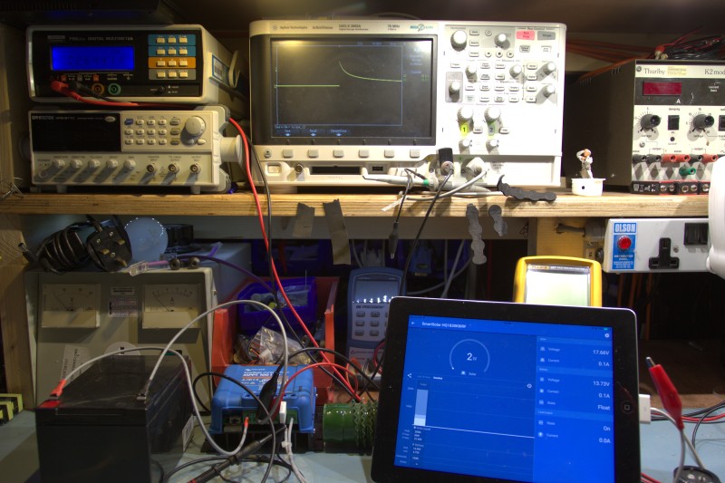
So I have an MPPT 100/20 with an AGM battery at its battery terminals, a fake solar panel in the form of a bench power supply with a big resistor (because there is no sun today).

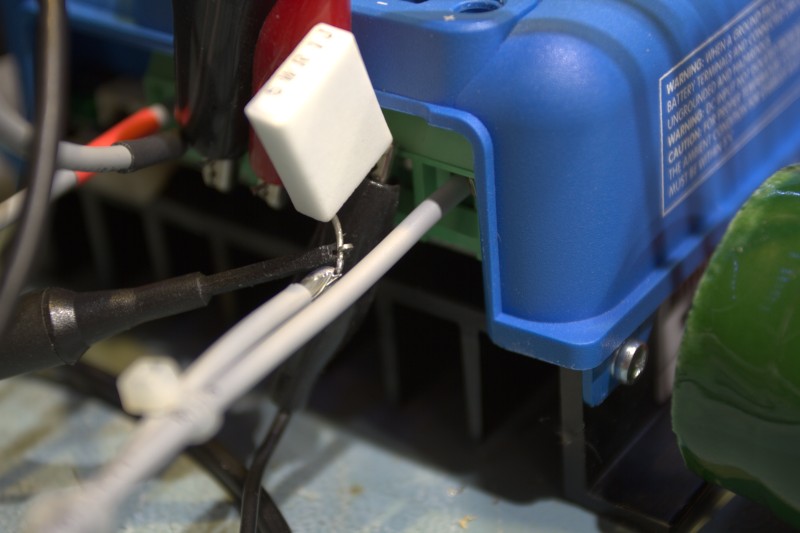
I am measuring the current that the Load output is supplying with my oscilloscope over a 0.1Ω shunt resistor.


So, let's measure how much current is flowing through the Load terminals and how long the MPPT takes to shut it down.

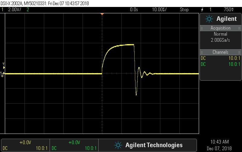
Here is a capture of the 21W brake lamp:
You can see that the initial burst of current peaks at about 12A, the filament heats up and the current tails off gradually over the next 100mS. Good, no problems.
Let's have a look at the 55W car headlamp:
This time, upon connection of the lamp, the inrush current peaks at about 40A and finally after around 15μS the Load switches off and this is reflected in the VictronConnect App. A second or two after disconnecting the lamp, the Load output is turned back on. I repeated ths a couple of times with similar disconnection timescales.

With a lower overload current (two 55W filaments in series), the current peaks at like 25A and the MPPT gives it some more time to clear, but when it has not done so after nearly 80μS then it disables the Load output.

Here I have just short circuited the Load output:
The short circuit current peaks at over 60A, and would have kept going, with a disconnection time of roughly 5μS - give or take.

So what?
Well, it seems that there is some "leniency" built in to try and allow for high inrush currents, but where do you draw the line. Too much leniency and then things blow up, too much and nothing works. Inductive loads are notoriously tricky and it's almost impossible to characterize all possibilities out there. From a design perspective there is only so much that can be done to keep with the budget constraints. The answer is to tricky loads drive a relay from the Tx port function, but then there is no metering of the load.
I know how I would get around this problem, but I don't think it's everybody's cup of tea.


img-4013.jpg (157.9 KiB)
img-4011.jpg (109.9 KiB)
scope-11.jpg (44.5 KiB)
scope-7.jpg (44.9 KiB)
scope-12.jpg (45.5 KiB)
scope-9.jpg (45.2 KiB)
1 comment
2 |3000

Up to 8 attachments (including images) can be used with a maximum of 190.8 MiB each and 286.6 MiB total.

brad-australia avatar image brad-australia commented ·

Hi Wkirby, What would you do to solve? and where are you geographically?

0 Likes 0 ·
Ray avatar image
Ray answered ·

Thanks mvader and wkirby, very comprehensive answers and illustrates exactly what I was doing.

So wkirby, what would you do, something with a relay, maybe a delay type relay?

Ray

2 |3000

Up to 8 attachments (including images) can be used with a maximum of 190.8 MiB each and 286.6 MiB total.

Peter Polz avatar image
Peter Polz answered ·

@WKirby : Sometims the easiest way to solve that problem in case of halogen lamps is with a simple NTC

2 |3000

Up to 8 attachments (including images) can be used with a maximum of 190.8 MiB each and 286.6 MiB total.

wkirby avatar image
wkirby answered ·

@Peter Polz : Yes, that will almost certainly work and will probably be the simplest. However, an NTC is the one thing that I can't find at the moment, I'm still searching my "scrap PCB cache" for an old SMPS which will certainly have one. I'd like to demonstrate it and try it on a motor.

So far, I have had success with a large inductor in series with the lamp and also a fancy automotive high side switch with automatic current limiting (BTS5016).

10 comments
2 |3000

Up to 8 attachments (including images) can be used with a maximum of 190.8 MiB each and 286.6 MiB total.

markus avatar image markus ♦♦ commented ·

@WKirby, @Peter Polz I could think of adding a big capacitor in parallel after the serial NTC; could help a fridge stay running.

1 Like 1 ·
wkirby avatar image wkirby ♦♦ markus ♦♦ commented ·

This will increase the inrush current though as the capacitor will initially appear as a short circuit.

I found an NTC, but it's 25°C resistance is a bit too high, so it gets too hot anyway.
I'm now experimenting with various fixed resistors to figure out a good value NTC at 25°C. It seems like something around 0.5Ω to 0.7Ω will be good. I will have to buy one and do some tests next week.

0 Likes 0 ·
markus avatar image markus ♦♦ wkirby ♦♦ commented ·

A was thinking of the NTC should lower the inrush current to the capacitor and the capacitor should deliver the start peak current to the fridge

0 Likes 0 ·
wkirby avatar image wkirby ♦♦ markus ♦♦ commented ·

Aha, I see your thinking, but since the capacitor will be beyond the Load Output (which is switched), then the capacitor will always be discharged (by the connected load) when the Load output is switched off. A heavy inrush current will flow in order to charge the capacitor AND power the load with its own inrush current characteristics.

What you are suggesting would work well if the switch is placed in between the capacitor and the load.

0 Likes 0 ·
markus avatar image markus ♦♦ wkirby ♦♦ commented ·

Good point.

But adding a relay to this circuit could be a solution. So we just developed a theoretical, community driven solution for this problem.

I like this very much :o)

0 Likes 0 ·
Peter Polz avatar image Peter Polz markus ♦♦ commented ·

There is nothing you have to develope :) A combination of resitor/ntc timer and a shorting relais is a regular softstart circuit :)

0 Likes 0 ·
markus avatar image markus ♦♦ Peter Polz commented ·

And, could be a solution to this problem. We did not invent a soft start circuit, but a theoretical solution. Thats what i meant papa...

0 Likes 0 ·
Ray avatar image Ray wkirby ♦♦ commented ·

Good thinking folks, in my case the fridge does its own switching on and off via thermostat so the NTC and Capacitor may work, and I'm not sure why the capacitor is needed, could you explain this?

Actually I think I see, the capacitor supplies start current to the motor while the NTC settles to a steady state, is this right?

Our Waeco fridge however is very sensitive to voltage sags so the right components would be important.

0 Likes 0 ·
markus avatar image markus ♦♦ Ray commented ·

The idea behind this is as you said.

I understand what you are thinking. But the Voltage should be almost(!) constant in this circuit, when the components are calculated in reasonable values. There should only be a delay, when the capacitor is fully charged initially.

If you chose not to use the capacitor, the voltage is not provided constantly, because the NTC raises the resistance in line to the fridge leading to a Voltage drop every time the fridge draws high peak current, the capacitor should smooth and settle this.

I hope this very theoretical sentence is somehow helpful...


0 Likes 0 ·
wkirby avatar image wkirby ♦♦ Ray commented ·

The capacitor will supply the instantaneous inrush (start) current to a load which is switched downstream of it. So it will be useful for supplying the inrush current as the fridge's thermostat switches on, but only if the Load output is on. The capacitor will become a hindrance though for the MPPT's Load output switching on though as it will need to be charged up as well as supplying the load.
I think just an NTC of the correct value will solve most of the problems. I have placed some in my shopping cart for my next Mouser order, which I will hopefully place this week.

0 Likes 0 ·
mvader (Victron Energy) avatar image
mvader (Victron Energy) answered ·

Hey all, sofar it still looks like the load output complaints (not starting large halogen lamps, not starting fridges) are all due to limitations of today’s design. I mean it’s not some software bug that urgently needs fixing.

But; we could look to see if it can be improved. By for example using more modern fets in the load output; increasing the (start-up) current. Or for example by buying a often use fridge that doesnt work today, and then testing/tweaking the system (if hardware allows it) to make the Short circuit protection allow its startup.

some questions; to see if we should start such project:

- why use halogen lamps? I would use led lamps instead in my motor home; so I don’t see any reason to spend R&D time on halogen lamps. (?)

- what fridge / compressors should we buy? Which are the popular ones in which geographical areas?

6 comments
2 |3000

Up to 8 attachments (including images) can be used with a maximum of 190.8 MiB each and 286.6 MiB total.

markus avatar image markus ♦♦ commented ·

Thank you so much for this! Never saw this type of cool, costumer related service somewhere else.

I would suggest to use a Danfoss BD35F compressor fridge as mentioned above not working. It's a very good and very common compressor.

0 Likes 0 ·
wkirby avatar image wkirby ♦♦ commented ·

It's quite tricky to design a solid state switch which drives a load of unknown characteristics. From your perspective it needs to act within the parameters of the fuse, slowing disconnect times may result in complaints of blown fuses.
Adding an NTC I think would work, I'll test this in due course. If the FET spent more time in the linear region at switch on it may reduce surges. Both of these probably require a new PCB revision.
An increasing PWM on the gate for a short period would be a firmware tweak provided there is enough CPU time to do this.
Just some of my ideas.

0 Likes 0 ·
Ray avatar image Ray commented ·

Excellent thinking mvader, I was only using the halogen lamp because it was about the same current draw as our Waeco bd35 fridge and easier to use ( and a simple resistive load). My thinking was if it can't run a lamp it won't run anything above a few amps.

My led light also connected to the load works perfectly but only draws 0.5 amps.

In australia Waeco and Engel fridges are very common, the bd35 and bd50 compressors would represent typical loads I think.

Now where is that box of old power supplies and parts...

0 Likes 0 ·
enorcs avatar image enorcs Ray commented ·

Here is an interesting thread on the danfoss compressor and soft starting. I have check exactly which controller my fridge has.

http://www.cruisersforum.com/forums/f115/fyi-new-danfoss-bd35-50-control-module-165725.html


0 Likes 0 ·
Ray avatar image Ray enorcs commented ·

interesting read , thanks. More thinking required here.

0 Likes 0 ·
brad-australia avatar image brad-australia Ray commented ·

I agree the Danfoss BD35 and BD50 compressors are the most common in 12v fridges. nearly all manufacturers use then except Engel and Bushman, which I believe have a lower draw and most like inrush currents.


0 Likes 0 ·
Justin avatar image
Justin answered ·

Hi

This is the fridge i am currently using , that i am having the same issue with


https://www.nationalluna.com/product/nl-52-weekender-refrigerator


2 |3000

Up to 8 attachments (including images) can be used with a maximum of 190.8 MiB each and 286.6 MiB total.

brad-australia avatar image
brad-australia answered ·

I've been using the 75/15 Bluesolar and Smartsolar on in vehicle installations with a fixed solar panel, Primarily running 12v fridges from the load output with no problems, I've been doing this for some time, and enjoy the consumption and yield data it provides. When the 100/20 was released I quickly purchased several to switch over to the 20a supply as this was preferred for faster charging. However, I too like so many of you found the load output would switch off, What I found was it would run fine for a period then stop. I had to return them all and continue to use the 75/15. I was advised by Victron through the Disqus page that it was related to inrush current however, The 75/15 work fine. I'm very keen to figure out why and have it rectified as I was told the 100/20 has exactly the same inrush and short circuit protection as the 75/15 . Keen to Follow

2 comments
2 |3000

Up to 8 attachments (including images) can be used with a maximum of 190.8 MiB each and 286.6 MiB total.

enorcs avatar image enorcs commented ·

Brad, Were the units running the same firmware version?

0 Likes 0 ·
brad-australia avatar image brad-australia enorcs commented ·

Hi Enorcs, Sorry I missed your question, Yes same firmware.

0 Likes 0 ·
thanar avatar image
thanar answered ·

I believe this issue could be alleviated by using a large capacitor in series with an appropriate resistor to cap the capacitor charging current below the short-circuit protection limit. For example, if the limit is 20A and we're talking 24V, you should use a 1.2Ω resistor. That way, as soon as the charger output activates, the capacitor will charge up OK and then as soon as the compressor starts, the capacitor will provide the same 20A of current to the fridge.

4 comments
2 |3000

Up to 8 attachments (including images) can be used with a maximum of 190.8 MiB each and 286.6 MiB total.

markus avatar image markus ♦♦ commented ·

Isn't a capacitor in series an isolator to a DC circuit?

0 Likes 0 ·
thanar avatar image thanar markus ♦♦ commented ·

It is. I don’t mean put it in series to the load. The capacitor will be in series to the resistor, both in parallel to the load.

0 Likes 0 ·
Peter Polz avatar image Peter Polz markus ♦♦ commented ·

he ment a simple LowPass Filter also named RC filter. That will work in some sitation.

0 Likes 0 ·
Ray avatar image Ray commented ·

Yes, capacitor after the ntc might work well as has been mentioned somewhere in this thread or similar threads. The NTC I have in cct is 0.5 ohms so less restrictive than 1.2 ohm. Now just need time to look for a big enough capacitor.

Ray

0 Likes 0 ·
mvader (Victron Energy) avatar image
mvader (Victron Energy) answered ·

Hi all,

A long long time later, but I wanted to let everyone know that we closed the loop on this one.

After this discussion on community, our hardware team looked into the design and found a hardware improvement to make: improving how the load output handles inrush currents.

We found that (in the old design) the load output resets under the following scenario: the fridge is already on, desired temperature is reached thus the compressor stops working. As soon as the compressor starts again, a peak current of about 40A is drawn which is enough to trip the short-circuit protection of the load output. Once the short-circuit protection trips, the load output switches off and after a few seconds switches back on again (thus the fridge resets as well). At that point the current drawn was lower (close to 22A), so the fridge was working ok.

We kept the fridge running for 4 days (testing with different battery voltages, temperatures and even with the option of turbo cooling) and the above behaviour kept repeating.

Following those results, we improved the design, it now allows a higher startup current. Which we tested with said fridges & compressors, and also Ray tested it, already back in June 2019. And conclusion is that it works well.

Here are the serial numbers per when the (hardware) change was implemented:

  • SCC075010060R SmartSolar MPPT 75/10 Retail HQ1935
  • SCC075015060R SmartSolar MPPT 75/15 Retail HQ1935
  • SCC110015060R SmartSolar MPPT 100/15 Retail HQ1947
  • SCC110020060R SmartSolar MPPT 100/20 Retail HQ1911

The 100/20 that we currently ship from our warehouses has the improvement. As do the 75/10 and the 75/15. The 100/15 is still shipping with hardware from prior to this improvement, due to stock levels of older production batches.

11 comments
2 |3000

Up to 8 attachments (including images) can be used with a maximum of 190.8 MiB each and 286.6 MiB total.

randy-h avatar image randy-h commented ·

Thank you for the followup and improved hardware design. I will be searching out the 100/20 with the referenced serial number start points.

0 Likes 0 ·
bazbrush avatar image bazbrush commented ·

cct1.jpgA bit late to this thread I know, but my solution to the fridge start-up problem was very simple. The overcurrent limit on these units is obviously very fast acting and I notice a lot of people attempting to absorb the inrush current with NTCs etc. My approach, instead of trying to absorb high current peak, was to bypass the controller for around a second with a very simple circuit of only 4 readily available and cheap components. A brief sescription of the circuit: When the fridge compressor kicks in the current limit of the MPPT activates and the voltage starts to drop. This in turn switches the TIP36 on via a 1000uf and 6R8 resistor just long enough to supply the high inrush current at which point the MPPT controller takes over again. The TIP36 will handle 25A continuous, 50A peak so will easily handle the power needs of a fridge compressor. The 6R8 is just to limit the base current to 2A (limit for TIP36 = 5A) and the 10k is just to discharge the capacitor. I've had this running for months with no problem and can track all my loads in and out. Schematic attached.

0 Likes 0 ·
cct1.jpg (137.9 KiB)
100-20.jpg (97.1 KiB)
randy-h avatar image randy-h bazbrush commented ·

Thanks, bazbrush .

0 Likes 0 ·
bazbrush avatar image bazbrush randy-h commented ·

You're welcome randy-h!

0 Likes 0 ·
Ray avatar image Ray bazbrush commented ·

@bazbrush

Thanks bazbrush, I will give this a go on my son's 100/20 which was purchased before the upgrade to the 100/20.

Ray

0 Likes 0 ·
bazbrush avatar image bazbrush Ray commented ·

Cheers Ray, let me know how it works out.

Barry.

0 Likes 0 ·
Ray avatar image Ray bazbrush commented ·

@bazbrush @randy_h

I have tested the cct and it works well on my 4.5 amp halogen lamp that the old 100/20 does not like. However I noticed the load output must be set for always on otherwise the TIP 36 tries to power the load and gets very hot very quickly. Note I think I have the capacitor around the wrong way so I will try again.

0 Likes 0 ·
bazbrush avatar image bazbrush Ray commented ·

Hi Ray, connecting the capacitor the wrong way round would certainly hold the TIP36 on, cause it to power the load and overheat. Make sure the negative of the cap is connected to the load output and the positive to the 6R8.

On my own installation I have the load of the 100/20 set to always on, but it should still operate fine if it's not. Lowering the value of the 10k resistor will reduce the on time of the TIP36 and should alleviate any of the problems you mention. You should be able to go as low as 1k, although the 'on' time of the circuit might be a little short. If I get time in the next couple of days I'll see how my own 100/20 operates with the load output switched off.

Once again, let me know how you get on.

0 Likes 0 ·
Ray avatar image Ray bazbrush commented ·

@bazbrush @randy_h

OK, with correct components around the right way it works on the 50 watt halogen lamp. Short delay before it comes on if I switch it off and on. I also tried shorting it (not on the 100/20) by touching the load wire to battery negative and it seems happy. Would it try to conduct if connected to the 100/20 and the load was shorted out?

Next to test with the fridge.

0 Likes 0 ·
randy-h avatar image randy-h Ray commented ·

Thanks ray-pridham
I look forward to your fridge test results. I am going to start sourcing parts to build this. My 100/20 is the old style as well. Thank you too, bazbrush .

0 Likes 0 ·
bazbrush avatar image bazbrush Ray commented ·

Hi Ray. A general purpose diode connected across the 10k resistor will minimise, if not eliminate, the delay you mention ... I've added it to the schematic.

On your second point; as the operation of the circuit is momentary it would never try to conduct until the short was removed and the capacitor discharged ready for the next cycle.

Re your earlier point about the 100/20 output having to be always on. This circuit needs the output voltage to be present in order to work and absorb the surge. If the 100/20 is in an off state and attempts to start with something like a fridge connected you're back to square one as there's nothing to trigger the circuit.

0 Likes 0 ·

Related Resources

Additional resources still need to be added for this topic