question

Galin Radoslavov avatar image
Galin Radoslavov asked

Problem with AC current sensor 40 A

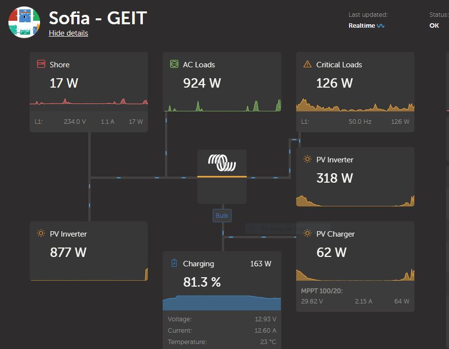
I have two PV systems. First is with MultiPlus 12/1600/70 and second one is MultiPlus II 48/5000/70 GX.

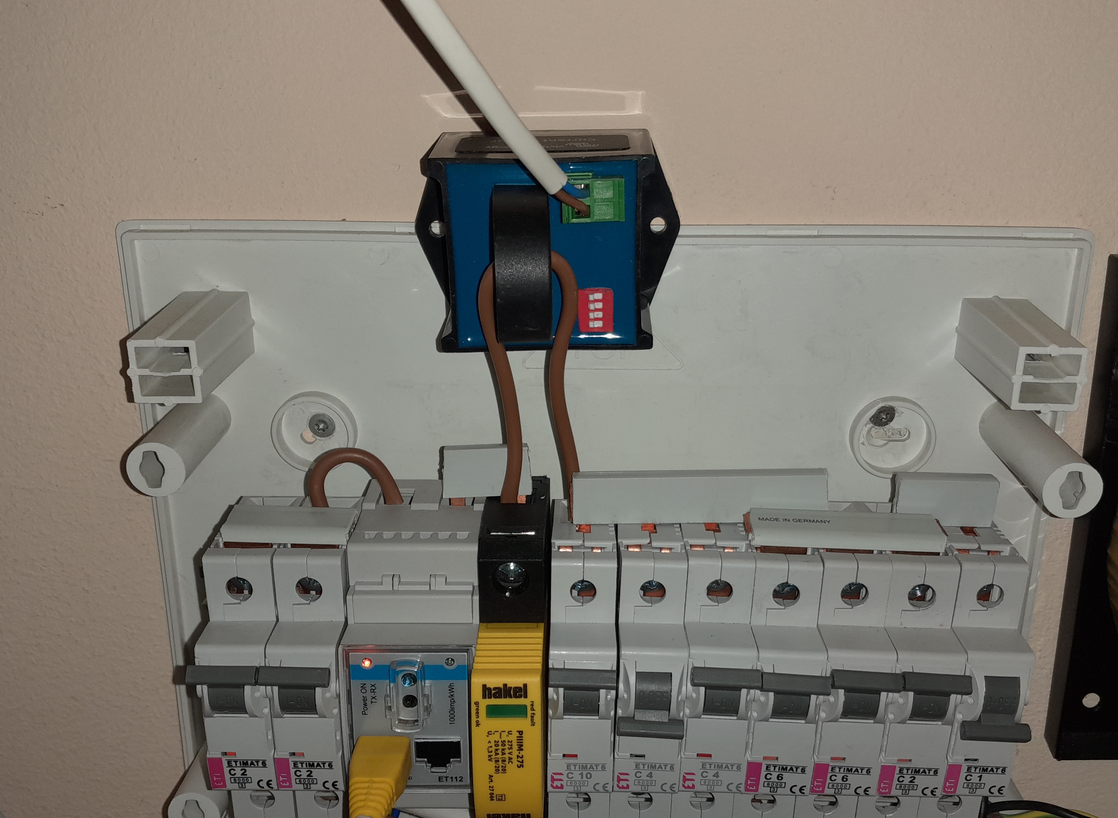
We have two different current sensors connect to the temp input of the both inverters.

Add AC current + ESS assistant. Upload to the each inverters. All last firmware. All requirements about main chip covered.

Restart Cerbo.

Wait 24 hours to calculate reactive currents and the values are not correct.

First I see that the measurement value is 350 W less than actual one. And the second the power of the PV inverter add to the AC load when is on input side or to AC critical loads when is on the output side.

I asked my local delaer - no answer. I ask in Romania - no answer.

Is anybody in this company to solve the problems?
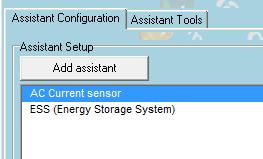
assistant.jpg


AC PV Coupling
assistant.jpg (16.0 KiB)
2 |3000

Up to 8 attachments (including images) can be used with a maximum of 190.8 MiB each and 286.6 MiB total.

10 Answers
Galin Radoslavov avatar image
Galin Radoslavov answered ·

I fix 48 V system without any help from Victron.

Nobody help me with 12 V system. - THE SUPPORT IN THIS COMPANY IS OUT OF ORDER..

2 comments
2 |3000

Up to 8 attachments (including images) can be used with a maximum of 190.8 MiB each and 286.6 MiB total.

frank-fahrenheit avatar image frank-fahrenheit commented ·

Hello Galin,

your original question is from Jan 2023

Being an electric engineer, I have to tell

you that your error description is useless.
No idea what is going on.
Guess this is why nobody, even from victron,
answered.

Then you say you fixed the problem with the 48V system.
No mention what you fixed, and what was wrong.
It is always helpful to understand the overall picture
when the guy having the problem tells what he/she has
tried and done in the meantime.

You did not do it.

Here my suggestion: you turn off the now working 48V system
and write a decent problem description of the 12V system

Greetings

0 Likes 0 ·
Galin Radoslavov avatar image Galin Radoslavov frank-fahrenheit commented ·

The 40 A current sensor DO NOT work with 12 V system with MP 12/1600 model.

Am I clear now?

0 Likes 0 ·
Galin Radoslavov avatar image
Galin Radoslavov answered ·

There months nobody help me with my MP 12/1600 and AC current sensor. There are new firmware MK3 and new release for Cerbo and thecapture.jpg same problem. Actual picture form today. input and output PV inverters are the same - input is with AC sensor - output is with meter. Wrong data all the time.
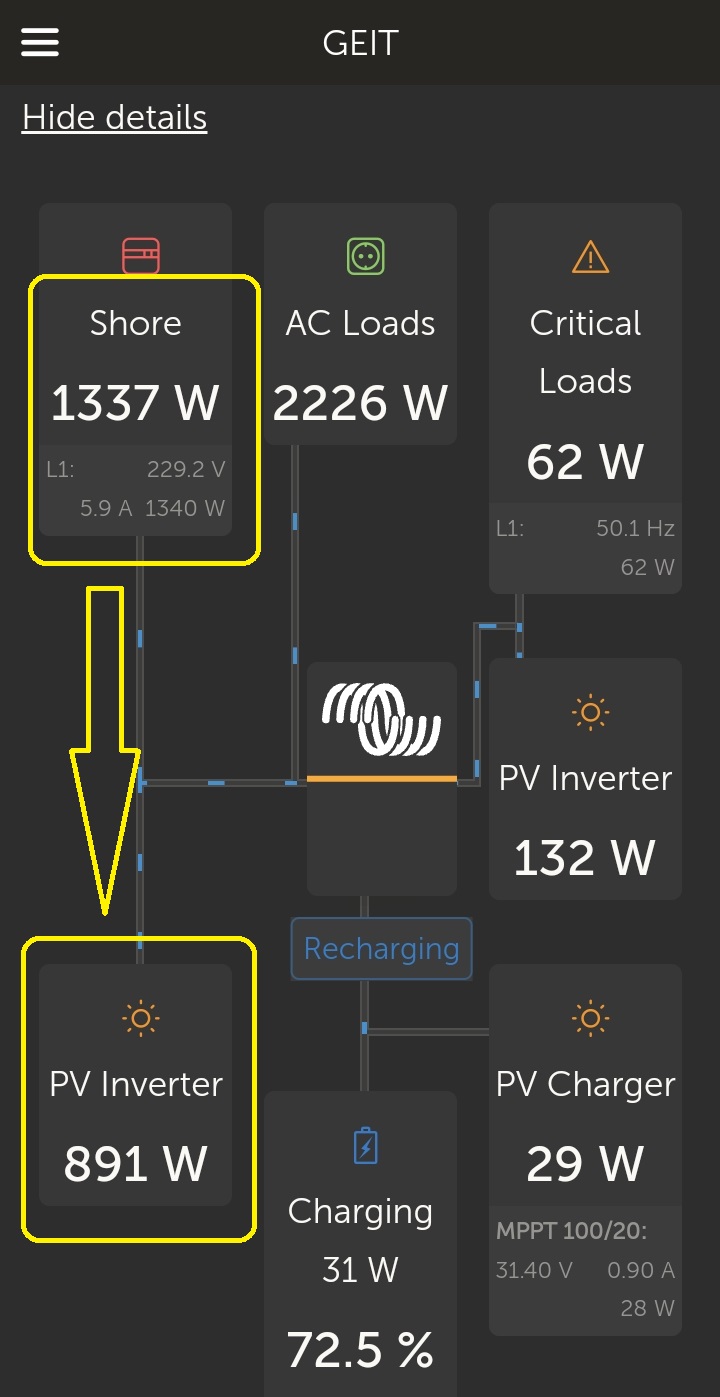
capture.jpg (53.4 KiB)
2 comments
2 |3000

Up to 8 attachments (including images) can be used with a maximum of 190.8 MiB each and 286.6 MiB total.

frank-fahrenheit avatar image frank-fahrenheit commented ·
is the 12V system off now ? If it is active I would not be surprised

that the sum of powers is not zero.

0 Likes 0 ·
Galin Radoslavov avatar image Galin Radoslavov frank-fahrenheit commented ·

Yes - my 12 V system work now

You can see

https://vrm.victronenergy.com/installation/108595/share/cbac5fcf

0 Likes 0 ·
Galin Radoslavov avatar image
Galin Radoslavov answered ·

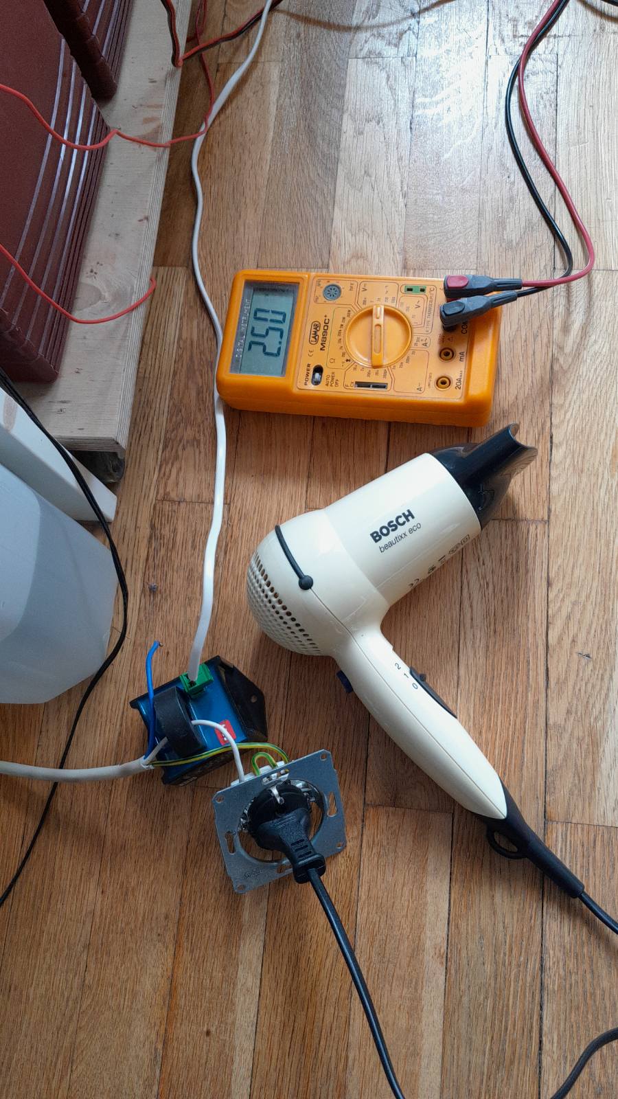
Test with other load instead of PV inverter. The load is 1300 W - grid meter measure 1300 W + small load in the system - AC current sensor measure 900 W. HELLO the problem is stil alive.

test2.jpgtest3.jpgtest1.jpg


test2.jpg (419.4 KiB)
test3.jpg (127.2 KiB)
test1.jpg (230.6 KiB)
2 comments
2 |3000

Up to 8 attachments (including images) can be used with a maximum of 190.8 MiB each and 286.6 MiB total.

frank-fahrenheit avatar image frank-fahrenheit commented ·
The yellow arrow that you have drawn makes no sense.

There is no power flowing INTO the PV inverter.


The cabling by the way is horrible, the yellow-green cable is used for EARTH.

0 Likes 0 ·
Galin Radoslavov avatar image Galin Radoslavov frank-fahrenheit commented ·
There is a problem not with cable. THE PROBLEM is that the current sensor measure 378 W less than the real value. Stop look colours and cables.
0 Likes 0 ·
Galin Radoslavov avatar image
Galin Radoslavov answered ·

Today 378 W less with AC sensor that grid meter05-march-23.jpg


05-march-23.jpg (72.9 KiB)
2 comments
2 |3000

Up to 8 attachments (including images) can be used with a maximum of 190.8 MiB each and 286.6 MiB total.

frank-fahrenheit avatar image frank-fahrenheit commented ·

How can anybody undertsand what we see here?
It looks like you have 2 PV inverters here, each producing power.

0 Likes 0 ·
Show more comments
Galin Radoslavov avatar image
Galin Radoslavov answered ·

New picture

20230305-191618.jpg


2 |3000

Up to 8 attachments (including images) can be used with a maximum of 190.8 MiB each and 286.6 MiB total.

Galin Radoslavov avatar image
Galin Radoslavov answered ·

New inverter - the same problem. Order a new sensor.

2 |3000

Up to 8 attachments (including images) can be used with a maximum of 190.8 MiB each and 286.6 MiB total.

Galin Radoslavov avatar image
Galin Radoslavov answered ·

NEW INVERTER 12/1600 AND NEW SENSOR - THE SAME PROBLEM

NEW INVERTER 12/2000 AND NEW SENSOR - THE SAME PROBLEM.

HEY VICTRON YOU HAVE A PROBLEM WITH 12 V MULTYPLUS INVERTERS

SOMEBODY WILL SOLVE THIS PROBLEM SOME DAY

2 |3000

Up to 8 attachments (including images) can be used with a maximum of 190.8 MiB each and 286.6 MiB total.

valdeira avatar image
valdeira answered ·

Did you manage to solve your problem?

2 |3000

Up to 8 attachments (including images) can be used with a maximum of 190.8 MiB each and 286.6 MiB total.

Galin Radoslavov avatar image
Galin Radoslavov answered ·

No. I am wating somebody to check the software inside Victron products

2 |3000

Up to 8 attachments (including images) can be used with a maximum of 190.8 MiB each and 286.6 MiB total.

Galin Radoslavov avatar image
Galin Radoslavov answered ·

who want to see the real cituation

https://vrm.victronenergy.com/installation/108595/share/cbac5fcf

2 |3000

Up to 8 attachments (including images) can be used with a maximum of 190.8 MiB each and 286.6 MiB total.