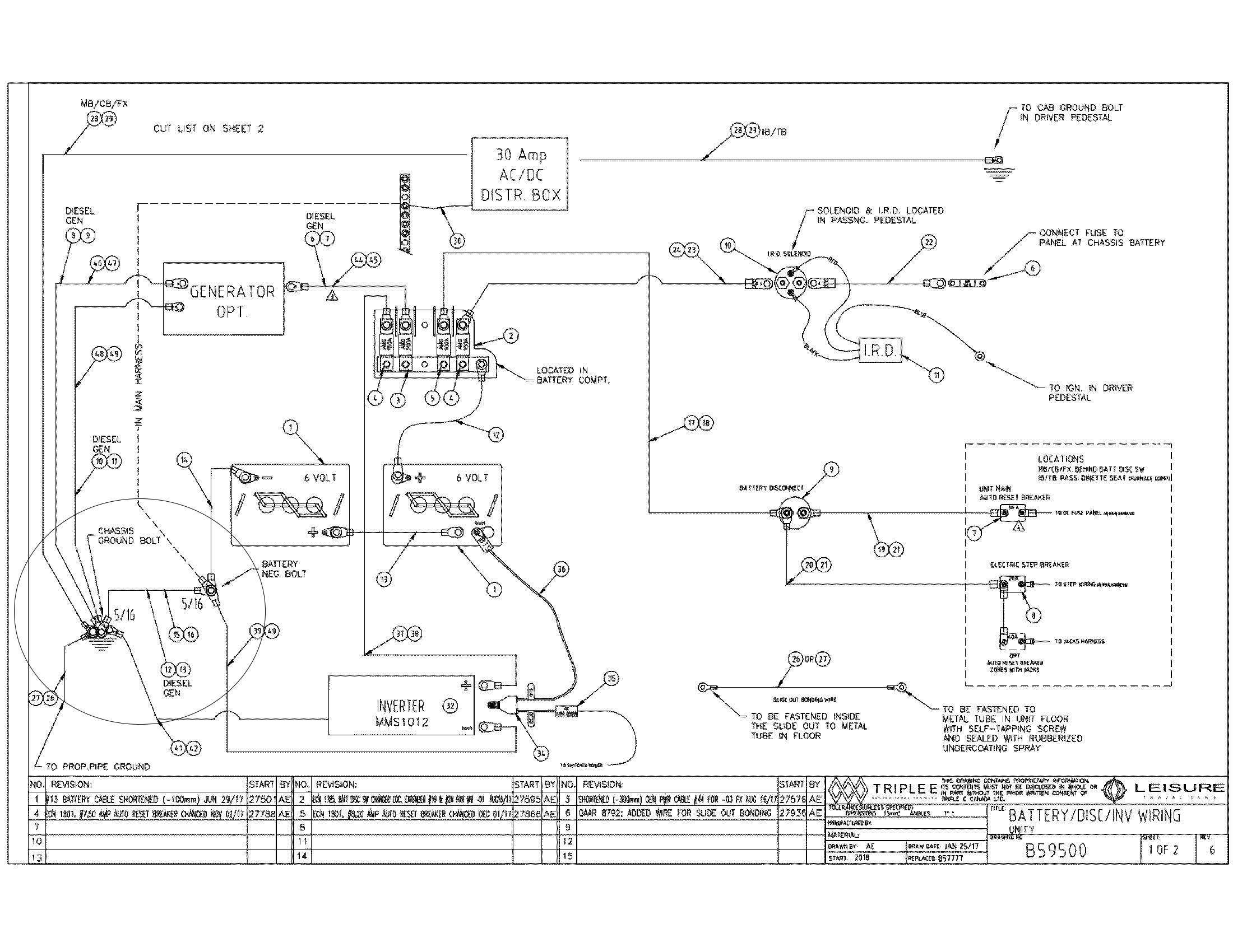
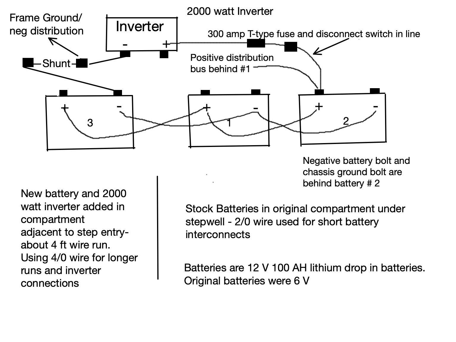
 See annotated drawing of a battery/inverter upgrade in which I am adding a 3rd 12 V lithium battery and larger inverter in a compartment adjacent to the OEM battery location under the step well. I am pondering the wiring of the shunt and inverter, trying to have balanced charging/discharging and capture of all DC loads on my BMV 702. Please critique the design for problems. I've tried to get around the wiring run issues by varying cable size (2/0 and 4/0) and picking the shortest runs possible. I have a particular question about the negative/frame connection. The original chassis ground and negative battery bolts are behind the batteries in the OEM battery box. Should I run a short cable from the distal end of the shunt to a nearby, nicely polished/bare metal frame ground or should I run a longer 4/0 cable back to the battery box to the negative distribution bolt(s) there? Isn't a new frame ground equivalent in function to the bolts in the battery box? See circled area on the RV's electrical schematic. This is in a Mercedes Sprinter-based Class C mobile home.
- Home
- Anonymous
- Sign in
- Create
- Spaces
- Grafana
- Node-Red
- Unsupported topics
- Questions & Answers
- Modifications
- Communauté francophone
- Deutschsprachiger Bereich
- Preguntas en Español
- Explore
- Topics
- Questions
- Ideas
- Articles
- Badges
question
Question about shunt wiring and frame negative/ground connections
battery-line-drawing.jpg
(389.9 KiB)
Comment
You could mirror the OEM design intent by running a 4/0 return back to the negative distribution bolts (there looks to be an awful lot of terminals on those two studs though, and as a general rule should limit # of ring terminals on studs).
On the other hand, I doubt you would run into problems by using the chassis as return as long as you have good contact. Kind of a toss up, I'd lean toward the latter.
I'm assuming that you're disconnecting existing link between battery -ve and the chassis, else return current would bypass the shunt?
Related Resources
Victron BMV battery monitors product page
Additional resources still need to be added for this topic
question details
7 People are following this question.
