question

rel avatar image
rel asked

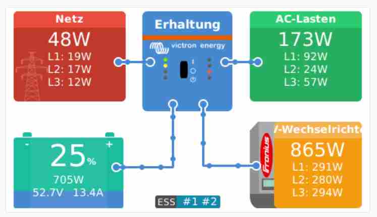
CCGX display - separate boxes for the loads?

Hello together,


as Newbie with Victron systems I have a question. I did not find an answer in the threads:
Our system is running well in the shown 3-phase configuration (3x Multiplus II with current sensors, Fronius Symo, BMZ storage, CCGX, system in ESS mode, two AC outputs: non UPS loads and UPS loads), but on the CCGX display there are never separate boxes for AC direct loads and critical loads as shown in the manual.

What setting has to be changed to get two separate boxes for the loads on the display?


Thanks for Infos!
REL
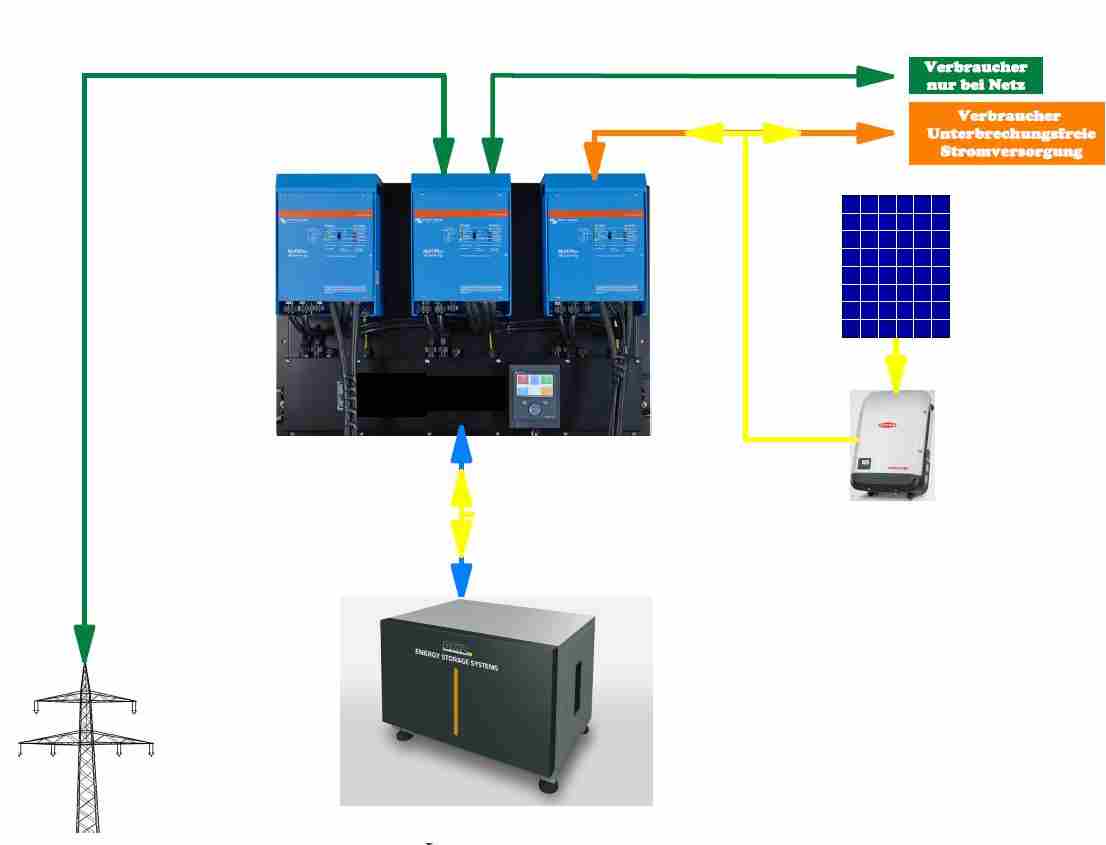
Multiplus-IICCGX Color Control
forum-victron-3.jpg (31.7 KiB)
ccgx-display.jpg (17.7 KiB)
1 comment
2 |3000

Up to 8 attachments (including images) can be used with a maximum of 190.8 MiB each and 286.6 MiB total.

rel avatar image rel commented ·

Here is an example of the critical loads display that I would like to show - CCGX Display Loads.jpg

0 Likes 0 ·
3 Answers
Guy Stewart (Victron Community Manager) avatar image
Guy Stewart (Victron Community Manager) answered ·

Hi Rel,

To seperate out the loads like that to critical and normal requires enabling the “Grid Meter Installed” setting in the ESS menu, and actually having an external energy meter installed.

Enabling this setting WITHOUT an external energy meter will display the separated load boxes, but will also put the system into passthru mode.

2 |3000

Up to 8 attachments (including images) can be used with a maximum of 190.8 MiB each and 286.6 MiB total.

rel avatar image
rel answered ·

Hello Guy,

thank you for the info!

So I need to install one Victron Energy Meter ET340 - 3-phase (datawise connected via RS485 to USB interface cable to the CCGX) and position it at the MPII AC outputs for "non UPS loads" (Verbraucher nur bei Netz)?

I suppose the "UPS critical loads" are measured internally?

Best regards

REL

2 |3000

Up to 8 attachments (including images) can be used with a maximum of 190.8 MiB each and 286.6 MiB total.

rel avatar image
rel answered ·

Hello again,


now a EM24 Energy Meter is installed between our Non-UPS loads and AC output 2 of the system.
An additional box "AC Loads" is visible on the CCGX since activating "Grid meter installed".
But there is a problem:
A.
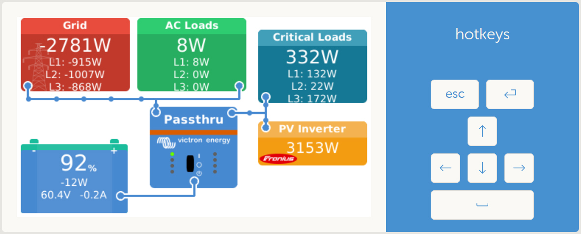
If the EM24 is configured as "Grid meter" in the menu "Energy meters" (as you suggested), the box "Grid" shows the AC output 2 and box "AC Loads" shows the Grid values and the system unwanted feeds battery power to the Grid.
B.
If I select type "Generator" for the energy meter instead of "Grid meter", then the Grid values are correctly displayed in box "Grid" and the EM24 values in box "AC Loads" (see screenshot), but after some time the system switches to "Passthru" operation.


I tried a lot of setting combinations, but either I get the values in the wrong boxes or the display is right, but the system runs in "Passthru".


Can you please give me a hint what settings are needed for correct system behavior?

How to disable "Passthru" if the display is correct?


Best regards


ccgx-em24.jpg (190.5 KiB)
3 comments
2 |3000

Up to 8 attachments (including images) can be used with a maximum of 190.8 MiB each and 286.6 MiB total.

rel avatar image rel commented ·

Feedback:
Tried a lot of things/configuration but even with the newest versions of firmware there was no change. Wrong display/behaviour of the system or "passthru".

So buying the EM24 was a waste of money.

0 Likes 0 ·

Hi @REL

Can you draw up a simple diagram of what you've connected where?

you mention a grid meter between ac-out2 and loads, that's not where a grid meter should be installed. A grid meter should be directly at the grid connection.


0 Likes 0 ·
rel avatar image rel Daniël Boekel (Victron Energy Staff) ♦♦ commented ·

Hello Daniël,


thank you for the reply.
As I understood, Grid input and AC output 1 are measured in my system by the internal current sensors of the Multiplus II - standard configuration with no external meter.
But I wanted to have an additional display for the AC output 2 (in "separat boxes") and just added an external EM24 between our Non-UPS loads and AC output 2 of the system.


Guy wrote that I have to configure the new EM24 as "Grid Meter" to get displayed separat load boxes, but then the box "Grid" shows the AC output 2 and the box "AC Loads" shows the Grid values. I did not succeed to configure it the other way round. Furthermore the system feeds battery power to the Grid, what is wrong for me.


But if I configure the new EM24 as "Generator" then the Grid values from the internal sensors are again correctly displayed in box "Grid" and the new EM24 values in box "AC Loads" (see screenshots in the other mails). But after some time the system switches to "Passthru" operation. Guy wrote, this is because no external Grid meter is found now. Despite the software uses the internal sensors and displays the correct value in the "Grid" box.


If the "Passthru" mode could just be switched to regular mode in the software settings, even if there is no external Grid meter found (this job is actually done by the internal input sensors), it would run here as I want to have it.


Best regards,

REL

0 Likes 0 ·