question

lintech avatar image
lintech asked

Why did Multi RS Solar ESS discharge below the minimum SOC?

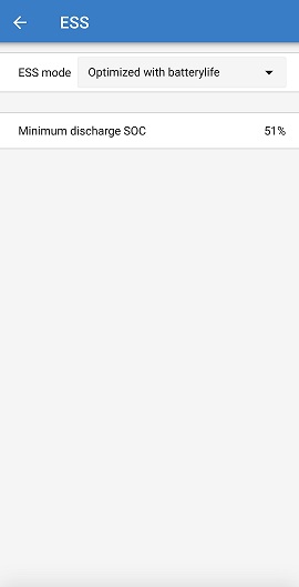
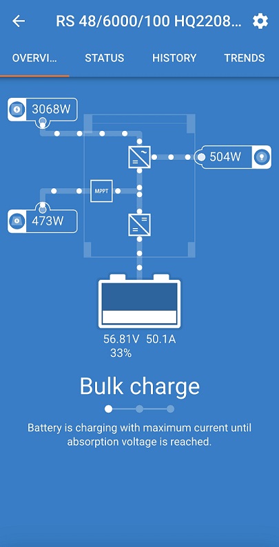
When you setup a Multi RS Solar with ESS set to "Optimized with Battery Life" and the Minimum SOC is set to 51%, is this supposed to limit the battery discharge to a minimum of 51%? Reason I ask is that I checked my system this morning and the batteries had discharged to 33%. My concern is that although the grid started charging the batteries, I have no idea how low my batteries would have dropped to (No History on SOC). Is this a fault with the setup or the algorithm?
ess-1.jpgess-2.jpg


solar
ess-1.jpg (13.0 KiB)
ess-2.jpg (61.2 KiB)
2 |3000

Up to 8 attachments (including images) can be used with a maximum of 190.8 MiB each and 286.6 MiB total.

11 Answers
Guy Stewart (Victron Community Manager) avatar image
Guy Stewart (Victron Community Manager) answered ·

Hi @lintech,

That minimum SOC value only applies when the grid is available. I will make a note to the VictronConnect dev to add this detail to the app to make it clearer.

If the grid is not available then the battery will continue to discharge down to the DC voltage cut-off point, in an attempt to power the loads for as long as possible.

This is normal, and desirable operation. For most in ESS the grid is fairly reliable and they want to cycle their battery daily. However they also want some backup capacity from their battery in case the grid goes down.

This setting allows you to set how much is cycled, and how much is left in reserve for when the grid is disconnected.

Then the priority is to run the loads without interruption for as long as possible.

The DC battery voltage cut off point is then next safety mechanism to protect the batteries from being excessively discharged.

If the grid comes back, then the battery will recharge from the grid back to that minimum discharge point again, and for a full recharge you will need solar power.

2 |3000

Up to 8 attachments (including images) can be used with a maximum of 190.8 MiB each and 286.6 MiB total.

lintech avatar image
lintech answered ·

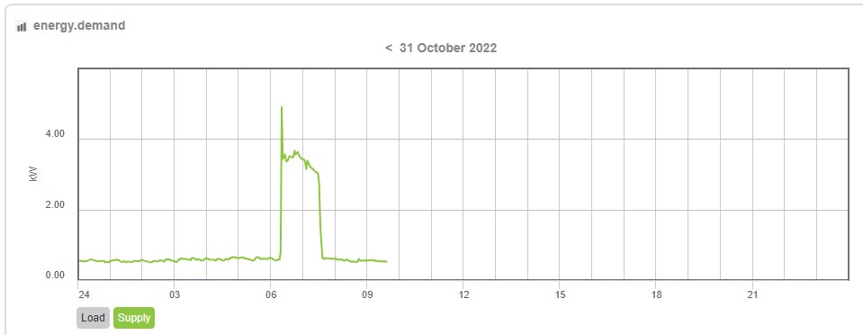
Hi @Guy Stewart (Victron Community Manager) the Grid was connected at the time. Not sure why the grid charger was activated though, unless it does this if the SOC or battery voltage get to a low level.

supply-trend4.jpg


supply-trend4.jpg (34.3 KiB)
2 comments
2 |3000

Up to 8 attachments (including images) can be used with a maximum of 190.8 MiB each and 286.6 MiB total.

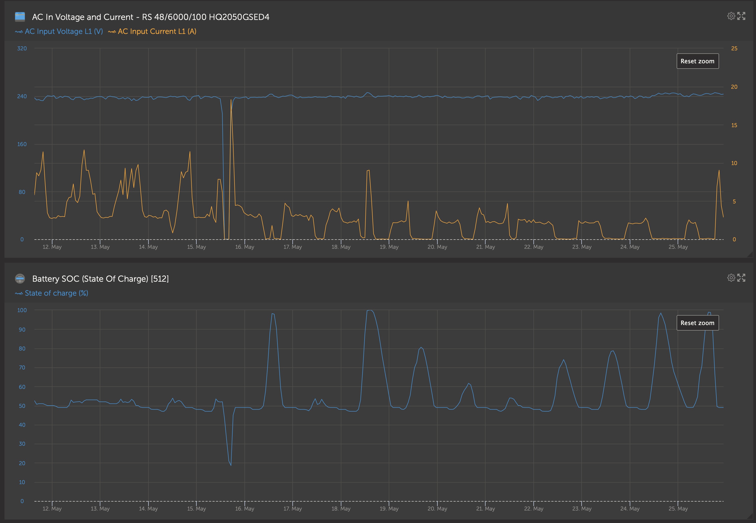
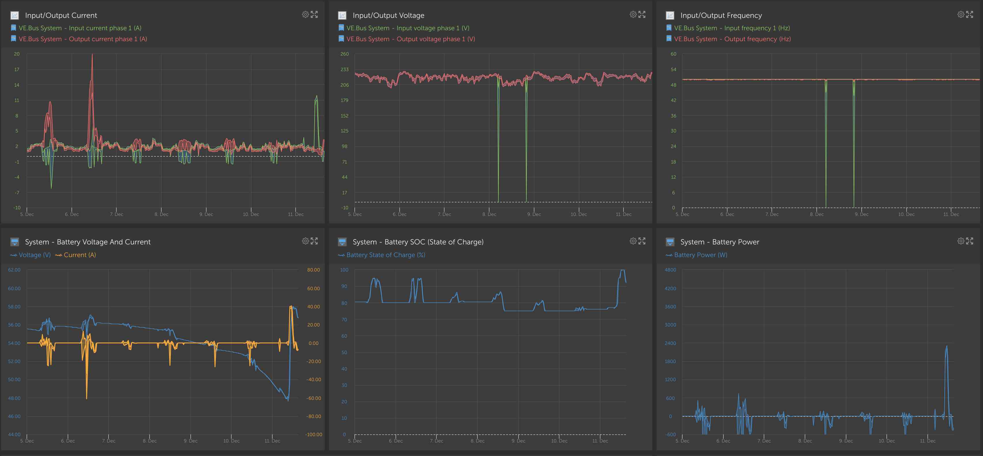
Here is an screenshot from VRM of a similar RS system - could you create the same one with the state of charge beside the AC input voltage and current measured at the Multi RS?

cleanshot-2022-10-31-at-132038.jpg

0 Likes 0 ·
energie-utechnik avatar image energie-utechnik Guy Stewart (Victron Community Manager) ♦♦ commented ·
Hallo Guy,
woher kommt diese Anzeige genau, von ein Multi Rs Solar über VRM ? Ich versuche momentan vergebens die Ac In Werte auf dem Global link einzusehen, leider vergebens.
MfG Schroeder Daniel
0 Likes 0 ·
lintech avatar image
lintech answered ·

Hi @Guy Stewart (Victron Community Manager) that must be via a GX unit which I don't have. The VictronApp does not have the Trends working and SOC is not part of the history anyway so unfortunately, I can only show what is available to me.

1 comment
2 |3000

Up to 8 attachments (including images) can be used with a maximum of 190.8 MiB each and 286.6 MiB total.

Without that info I am not sure it’s possible to determine if the system operated correctly, or at least where the issue might be.

Is it re-occurring or just a once off and normally behaves as described above?

0 Likes 0 ·
Ingo avatar image
Ingo answered ·

According to the link below, a GX device is a required component of ESS.

https://www.victronenergy.com/upload/documents/Energy_Storage_System/ESS_design_and_installation_manual-en.pdf


2 comments
2 |3000

Up to 8 attachments (including images) can be used with a maximum of 190.8 MiB each and 286.6 MiB total.

Hi @Ingo,

You're correct, but it's also a little bit more complicated than that.

Officially the Multi RS does not support ESS mode at all right now - only VE.Bus equipped inverter/chargers - The Multi RS is VE.Can (with no VE.Bus) - https://www.victronenergy.com/media/pg/Multi_RS_Solar/en/general-description.html#UUID-d0410677-d6c3-4857-b838-241843379f7a

It is still a new product and there is still a lot of active work underway (which is one of the reasons I have jumped in here).

There is a VERY BASIC ESS function built into VictronConnect for the Multi RS - there are a great many other ESS features still missing (i.e no export, no scheduled charging, no grid codes/certificate approvals, etc), and they are often built around the controls available in the GX device.

What is being described by lintech here IS within that very basic feature set that is already enabled though - the ability to stop discharging at a certain state of charge, and then use AC input power instead, until the AC input is disconnected, then use the remaining charge.

1 Like 1 ·
Ingo avatar image Ingo Guy Stewart (Victron Community Manager) ♦♦ commented ·
Thanks for the claritication. I see the ESS limitation in the link you provided.
0 Likes 0 ·
lintech avatar image
lintech answered ·

Hi @Ingo & @Guy Stewart (Victron Community Manager) looking at the ESS manual it seems that it is not working as defined although I accept that the Multi RS is "special" due to being a new product.

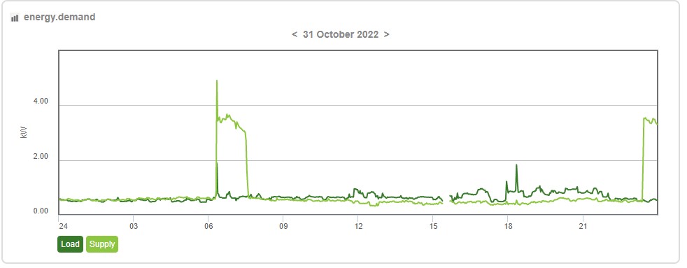
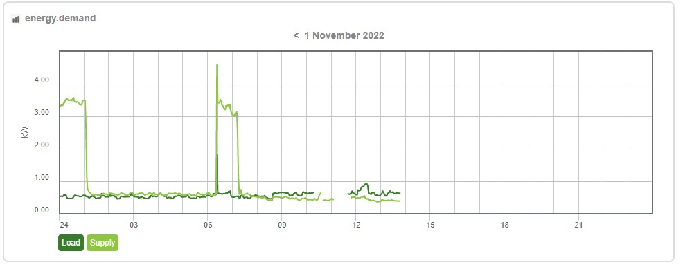
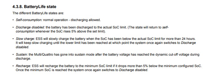
Below is my trend(s) for the inverter AC supply which shows that the inverter went into charge mode for about 1.5 hours at around 11:30pm and again at 6:30am. The description of the ESS manual indicates the inverter could go into charge mode if the SOC dropped 5% below the minimum state of charge setpoint, then off again once it is 5% above the SOC setpoint. 3kW of charging for 1.5hours from 50% SOC with a 210Ah battery set would make it fully charged not 5% over minimum setpoint.

supply-trend6.jpg

supply-trend7.jpg

batterylife-state.jpg

The operation I expected was that the batteries would discharge until they reached the low SOC setpoint then switch to AC. No charging would happen then until the next day when solar charging would commence. If the AC went off before the next day, the inverter would disregard the low SOC setpoint and discharge until either the AC returned, the battery voltage dropped below the shutdown setpoint, or the Solar was available to supply the load and charge the batteries. Question is, is this how it is supposed to work, or does it work under a "special" methodology because it is a new product?

With regards to the GX device, I have no problem spending another $500 if this will make it work properly although it would have been nice to know beforehand. Question is, will adding the GX device make the functionality and trending etc any better? What additional functionality will I get from the GX device or is any additional functionality only available on existing established products.


supply-trend6.jpg (40.0 KiB)
supply-trend7.jpg (45.0 KiB)
2 comments
2 |3000

Up to 8 attachments (including images) can be used with a maximum of 190.8 MiB each and 286.6 MiB total.

nickdb avatar image nickdb ♦♦ commented ·
The GX won't help you beyond having data uploaded to VRM and providing some remote access.

Is the firmware current on your device?

I don't use RS's, but in a conventional (full featured) ESS, it would work as you're expecting.

If you have batterylife enabled perhaps try use the mode without it.

0 Likes 0 ·
Show more comments
lintech avatar image
lintech answered ·

@nickdb & @Ingo thanks for the reply, I suspected that might have been the case, however I wasn't sure if the GX device enhanced the ESS control somehow. Firmware should be up to date as this is determined by the Victron Connect App as the firmware was upgraded when I first installed the app.

Guess I will have to wait and see what improvements come through in the near future. Just not keen on waking up with no power because things don't work as described.

2 comments
2 |3000

Up to 8 attachments (including images) can be used with a maximum of 190.8 MiB each and 286.6 MiB total.

nickdb avatar image nickdb ♦♦ commented ·
I’m sure @Guy Stewart (Victron Community Manager) will chime in.
0 Likes 0 ·
Hi @lintech,

I am biased but I do think that a GX device is an extremely worthwhile addition to *almost* every Victron system.

In this specific case, It will not solve your issue directly.

HOWEVER it would provide the necessary info for you, or I, to do the next steps in a diagnostic troubleshooting to see WHY the system is not behaving as expected, and what might be able to be done about it.

There is also an upcoming improvement to the Multi RS firmware that improves the AC input acceptance and control - this isn't specific to your issue here, but it might help, having the GX device would provide more confidence if that is likely to be a solution or if we need to be looking elsewhere.

A GX device is also worthwhile for many other reasons, and I am I confident that you would get value from it.

0 Likes 0 ·
lintech avatar image
lintech answered ·

@Guy Stewart (Victron Community Manager)

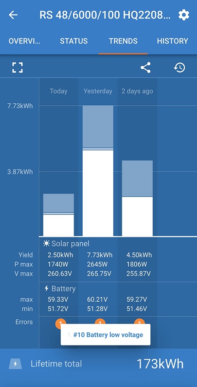
In your last reply you answered the question with the assumption that there was no AC available, however that has not been the case. It seems that the minimum SOC setpoint is being ignored and the batteries discharged until the low voltage setpoint is reached at which time the batteries are then being fully charged ready to cycle again. This is reducing the life of my batteries by excessive cycling,

*****************************************************************************************************

Hi @lintech,

That minimum SOC value only applies when the grid is available. I will make a note to the VictronConnect dev to add this detail to the app to make it clearer.

If the grid is not available then the battery will continue to discharge down to the DC voltage cut-off point, in an attempt to power the loads for as long as possible.

This is normal, and desirable operation. For most in ESS the grid is fairly reliable and they want to cycle their battery daily. However they also want some backup capacity from their battery in case the grid goes down.

This setting allows you to set how much is cycled, and how much is left in reserve for when the grid is disconnected.

Then the priority is to run the loads without interruption for as long as possible.

The DC battery voltage cut off point is then next safety mechanism to protect the batteries from being excessively discharged.

If the grid comes back, then the battery will recharge from the grid back to that minimum discharge point again, and for a full recharge you will need solar power.

*****************************************************************************************************

trend2.jpg

As can be seen from the connect app, the low voltage setpoint (52.0V) is being reached every night.

My original question was as per below, but your reply did not answer the original question.

*****************************************************************************************************

The operation I expected was that the batteries would discharge until they reached the low SOC setpoint then switch to AC. No charging would happen then until the next day when solar charging would commence. If the AC went off before the next day, the inverter would disregard the low SOC setpoint and discharge until either the AC returned, the battery voltage dropped below the shutdown setpoint, or the Solar was available to supply the load and charge the batteries. Question is, is this how it is supposed to work, or does it work under a "special" methodology because it is a new product?

*****************************************************************************************************

Can you please verify if the inverter is supposed to work as I have detailed above when ESS is set to "Optimized with battery life" and a SOC minimum setpoint of 51%? If not, can you please detail the expected functionality of this mode.

Regards Trevor


trend2.jpg (70.2 KiB)
1 comment
2 |3000

Up to 8 attachments (including images) can be used with a maximum of 190.8 MiB each and 286.6 MiB total.

Hi @lintech,

What you have described is how it is intended to work. I understand that it is not appearing to be the case in your installation, but I think I need the additional information provided by a GX device to identify any more information about why.

Another variable is when using 'with battery life', that it may adjust that SoC minimum set point threshold higher if the battery is not receiving a full charge. It may be worth using 'without battery life' to at least remove this as a possibility for your testing.

There is no deliberate different/special methodology with this new ESS implementation. Only to note that it is not yet considered complete.

0 Likes 0 ·
Guy Stewart (Victron Community Manager) avatar image
Guy Stewart (Victron Community Manager) answered ·

Some good news @lintech,

We have found something that would explain the behaviour you've seen - nothing else specific to report yet - but certain to be improved in a future update to better match the expected behaviour.

Thanks for your report.

1 comment
2 |3000

Up to 8 attachments (including images) can be used with a maximum of 190.8 MiB each and 286.6 MiB total.

Alexander Bartash avatar image Alexander Bartash commented ·
Hi. Do you have any ETA on the fix? I think I have the same issue. Thank you.
0 Likes 0 ·
lintech avatar image
lintech answered ·

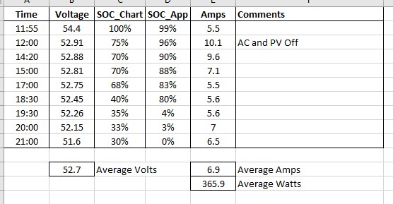
Thanks @Guy Stewart (Victron Community Manager), I spent yesterday evaluating a few things including testing the capacity of my batteries which is another issue I have to sort out. Correct me if I'm wrong but a 210Ah 48V battery set should last at least 20 hours with an average discharge of 7 amps. So far this has been disappointing all round.

I isolated the PV and the AC to see how long the batteries would last on an average load which also produced some other interesting issues. How is the SOC display calibrated as the SOC was linear (although inaccurate) till voltage dropped below 52.45V then it dropped to 4% in the space of 0.2V.

batt.jpg

How can I get the SOC value to display "accurately"?


batt.jpg (50.5 KiB)
2 comments
2 |3000

Up to 8 attachments (including images) can be used with a maximum of 190.8 MiB each and 286.6 MiB total.

nickdb avatar image nickdb ♦♦ commented ·

What battery is this? If it is a managed battery, then the SOC is solely provided by the BMS so you would need to start there.

If not, a shunt might be a good idea.

That

0 Likes 0 ·

b75f8211-8295-4c3d-a2aa-ac7ab4a3b1a3.jpegHi @lintech,

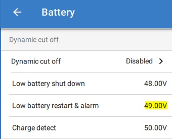
The current behaviour you are seeing occurs when hitting the programmed battery low levels:

warn = 5%

alarm = 0%

Check if this matches with the low battery settings.

This is not yet documented, and may change in the future.

0 Likes 0 ·
lintech avatar image
lintech answered ·

Hi @nickdb the batteries are 8 x Atlas 105Ah LifePo4 connected in a 4S2P 48V arrangement to give 210Ah, which have their own individual BMS. These are not Victron batteries with a Victron BMS.

https://www.aussiebatteries.com.au/atlas-105ah-12v-lithium-prismatic-deep-cycle-battery-australian-made


1 comment
2 |3000

Up to 8 attachments (including images) can be used with a maximum of 190.8 MiB each and 286.6 MiB total.

nickdb avatar image nickdb ♦♦ commented ·
That is going to make it a little more exciting for you.

You would be better served to integrate an external shunt that can be set (and subsequently tuned) for these batteries so you can have a more reliable SOC.

Internal BMS's (or any BMS for that matter), aren't always accurate so a bit of adjustment of the system may be needed. The internal inverter SOC calculation might be a bit off at present.

0 Likes 0 ·
Alexander Bartash avatar image
Alexander Bartash answered ·

@Guy Stewart (Victron Community Manager) Hi. I think I am seeing the same behavior with multiplus 5kva and smart solar 450/200. If I can help gathering some logs, metrics etc. Please let me know.

Also is there something I can do to mitigate this? E.g. install smart shunt or something else? I do not really want to set it to "Keep batteries charged" because I'd like to use sun energy efficiently and minimize grid usage because we do not have lots of that energy available currently in Ukraine's grid. At the same time I'd like to have some spare battery charge in case I loose grid, which can happen at any time for obvious reasons as well.
selection-936.jpg


selection-936.jpg (185.4 KiB)
2 |3000

Up to 8 attachments (including images) can be used with a maximum of 190.8 MiB each and 286.6 MiB total.

Related Resources

Additional resources still need to be added for this topic