question

Melih Manisalıgil avatar image
Melih Manisalıgil asked

3-Phase 45kVA Quattro Marine Solution Multiple BMS Configuration for Large Setups

  • I am designing a 3-phase 45kVA marine system with 3 parallel 48V/15kVA Quattro's.
  • The DC energy storage will be 218kWh at 48V (~4500Ah) while using LFP Batteries.
  • My challenge is that I can't decide how the BMS will took place because of the 5 parallel limitation of Victron BMSes. (Data communication limit)

This is a Victron setup in Romania for a furniture factory using 20 pieces of 25,6V/200Ah Victron LFPs for backup energy storage. But I don't see any BMS in the setup, it probably will be managed via existing SCADA.

So, the €/kWh cost for LFP is slightly higher in Victron LFPs but this is not the concern. MG Energy LFP280 with a single Master LV will be the most feasible. But, I can only use Victron solutions at the moment.

My question is that how the 5+ pieces of LFP batteries can be managed my Victron BMSes?

Maybe I can parallel multiple VE.Bus BMS V2 together for parallel operation but I don't know how to parallel control Quattro's with multiple BMS setup. Maybe this can be programmed in GX device for such configuration.

Practical suggestions much appreciated, thank you.


Lithium BatteryBMSinstallation
2 |3000

Up to 8 attachments (including images) can be used with a maximum of 190.8 MiB each and 286.6 MiB total.

10 Answers
thanar avatar image
thanar answered ·

Do all BMSs talk to the units when you have the maximum 5 parallel battery modules? I really believe this is overkill. Most modern battery designs only have one BMS-equipped unit anyway, afaik.

2 |3000

Up to 8 attachments (including images) can be used with a maximum of 190.8 MiB each and 286.6 MiB total.

hardy-tuner avatar image
hardy-tuner answered ·

Maybe u check for another bms, so a secondary bms is connected to a primary bms which conected to victron, like batrium.

2 |3000

Up to 8 attachments (including images) can be used with a maximum of 190.8 MiB each and 286.6 MiB total.

Melih Manisalıgil avatar image
Melih Manisalıgil answered ·

@thanar @hardy tuner Yeah, one BMS will be master and the others are will be slave in such parallel BMS configuration. Grouping 5 batteries with one master BMS and powering up one busbar seems like another option.

The installation example I shared was similar to my setup. 20 pieces of 25,6/200Ah Victron LFPs are used. But there is no visible BMS, this frustrated me.

1 comment
2 |3000

Up to 8 attachments (including images) can be used with a maximum of 190.8 MiB each and 286.6 MiB total.

Melih Manisalıgil avatar image Melih Manisalıgil commented ·

MG Energy have installed a similar project in 2016. They grouped the LFP batteries, and each group managed by seperate BMS (MG Master LV)

https://www.mgenergysystems.eu/2016/09/30/mg-provides-power-and-backup-for-mali-hospital/#specs

Running a hospital in Mali (Africa) is no easy feat, let alone without a reliable power supply. But there is plenty of sun. MG installed solar panels and a large capacity system to be used as a backup system. In total 46 Lithium-Ion LFP battery modules are divided over 4 banks, each supervised by a MG Master LV 600A and connected to one bus-bar system. Aditionally 12 Victron Quattro 10k units are installed to provide 120 kW / 3 phase power. This setup provides the hospital with energy, even during blackouts. No more diesel-fueled generators, but a dependable, self-sufficient and sustainable solution.

0 Likes 0 ·
Trevor Bird avatar image
Trevor Bird answered ·

@Melih Manisalıgil ...I am not sure about the battery configuration requiring 5 BMS units. The VE.Bus BMS V2 can handle 5 parallel strings so your system will be fine.

The size of the system eliminates the use of a shunt so the Quattros could be configured as the Battery Monitors. No "DC System" exists so that will be accurate.

One VE.Bus BMS V2 can handle the entire bank. VE.Bus control from VE.Bus BMS V2 to the first Quattro and daisy chain VE.Bus to each other Quattro. Connect VE.BMS V2 to CerboGx. Set up 3 Quattros on 3 Phase configuration. Set up battery bank to terminate to a large Busbar with individual series string fusing. It has serious DC fault current capability so obviously busbars must be well segregated and well designed.

3 comments
2 |3000

Up to 8 attachments (including images) can be used with a maximum of 190.8 MiB each and 286.6 MiB total.

Melih Manisalıgil avatar image Melih Manisalıgil commented ·

@Trevor Bird thank you, this way the system seems optimal for operation.

But I want to clarify that I am using 52 pieces of 12.8V/330Ah. Each bank has maximum of 5 parallel groups and the each bank will have seperate VE.Bus BMS V2 and these BMS'es will operate parallel. It seems one BMS can not handle the entire 52 pieces obviously.

So is it correct to chain BMS'es like this:

BMS (Master) -> BMS (Slave) -> BMS (Slave)

BMS (Master) -> Quattro (L1) -> Quattro (L2) -> Quattro (L3) -> Cerbo GX

Product Configuration Total # System Voltage (V) Total Capacity (Ah) Total Capacity (Wh)
Victron 12,8V / 330Ah 2 bank: 4 series, 4 parallel
1 bank: 4 series, 5 parallel
(3 banks total)
52 51,2 4290 219648


0 Likes 0 ·
Show more comments
echidna avatar image
echidna answered ·

It's not clear to me that the limit is (just) BMS-related. The Lithium Smart battery manual states:

"Connect a maximum of 5 batteries or battery strings in parallel", and "Connect a maximum of four 12.8V batteries or a maximum of two 25.6V batteries in series".

This would limit you in a 12V system to 5 batteries in parallel (5 total); in a 24V system composed of 25.6V batteries to 5 in parallel (5 total), or if composed of 12.8V batteries, to 2s 5p (10 total); in a 48V system composed of 25.6V batteries to 2s 5p. or with 12.8 batteries to 4s 5p (20 total).

There is no mention of building a bigger bank than these limits permit, although the example quoted in Romania would seem to considerably exceed these limits.

Why the 5-parallel limit (independent of system voltage)? The only thing I can think of is a concern about fault currents if a battery has a serious internal failure (which fault current should be limited by the individual fusing required for each string).


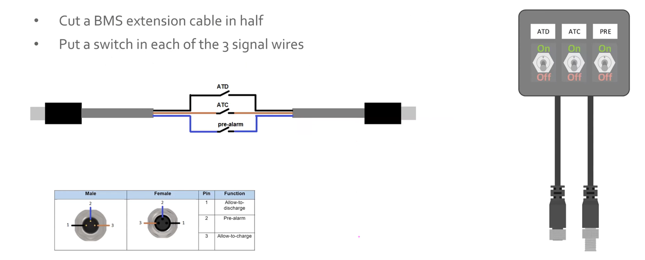
As I understand it, the BMS wires from the batteries have 3 conductors, and I believe there is normally continuity on each wire through the battery. The battery apparently signals an alarm condition by creating an open circuit on the appropriate wire (load disconnect, charge disconnect, or pre-alarm). Assuming the switch in the battery is a dry contact, I don't know why there would be a limit of 20 on the number of batteries that can have their BMS cables daisy-chained. Perhaps they use opto-isolators. Certainly the BMS wires must be galvanically isolated form the batteries to permit daisy-chaining of BMS cables from series-connected batteries.


It would be nice if Victron would clarify these various limits!


But assuming you can build a bigger bank (than 4s 5p 12.8V), and that the BMS is limited to 20 batteries, I would think you could use multiple BMS's, create some simple logic circuitry to combine the three electrical outputs of each BMS to make overall signals for the three alarm functions, and feed the overall load and charge disconnect signals into the Quattros using the Two-Signal BMS assistant. AFAIK, there is no way to do this using the VE.Bus outputs of the VE.Bus BMS.

2 comments
2 |3000

Up to 8 attachments (including images) can be used with a maximum of 190.8 MiB each and 286.6 MiB total.

Trevor Bird avatar image Trevor Bird commented ·
Yes @echidna , I am also very interested in the limitations quoted by many battery manufacturers on the “maximum” limit of series parallel connections. I can imagine too many in series may present a balancing problem but I cannot fathom why a parallel limit would be applied for technical reasons.
1 Like 1 ·
Melih Manisalıgil avatar image Melih Manisalıgil commented ·

Hi @echidna, yes Romania project is installed exceeded limits of Victron LFP batteries. But as I mentioned there is no visible BMS in the configuration, this is another question.

There is an explanation in Victron Lithium training (4.3.3 Troubleshooting) indicates the BMS cable wiring, if you are curios:

1666158829807.png


I think maximum limit derived from the maximum number of battery cells that BMS can handle. 25.6V batteries consists 8 cells, 12.8V batteries consist 4 cells. And the maximum cell count is same as 4s 5p (12.8V) and 2s 5p (25.6V) by 80 cells.

1 Like 1 ·
1666158829807.png (108.1 KiB)
echidna avatar image
echidna answered ·

Re the Romania video, you can see the daisy-chained BMS cables on the top row of batteries, but not where they go. They could have extensions to the equipment rack, etc. The Victron BMS's (Small or VE.Bus) are quite small, and could easily be hidden out of view.

Yes, I'm aware of that training video. That's what led me to believe that the BMS may be signaled by a simple open circuit inside the battery between the corresponding wires in the two BMS cables.

I suspect that the (external) "BMS" units Victron has are therefore rather "dumb". The real BMS is inside the battery, as part of the balancing and monitoring electronics. When you look at the VictronConnect app, all the BMS-type information is already available inside each battery: the individual cell voltages, the temperature, the alarm thresholds, etc., and the alarms derived from these.

My guess is that the only thing communicated by the battery through its BMS cables is those three alarm statuses, signaled by a simple open circuit in an otherwise continuous wire. (That is, there is no sophisticated digital communication mechanism, like CANBus being employed.) The external BMS then has no knowledge of individual cell statuses, or how many cells there are. Nor does it know which battery in a daisy-chained group is causing the alarm. It can't distinguish e.g., whether a high cell voltage or a high temperature or even a low temperature is causing a "charge disconnect" alarm. To get this information, you need to use the VictronConnect app to get the detailed data via Bluetooth from the batteries That is where the sophisticated communication occurs with the battery. Again, this is just my theory based on what information I've been able to find. I'd be interested to hear any further thoughts on this subject.


BTW, your argument about cell count fails to explain the maximum limit of 5 12.8V batteries in parallel - that is only 20 cells. The 80 cell limit you proposed would permit 20 12.8V batteries in parallel.

I should also amplify my thought about the paralleling limit. When you have paralleled batteries, it is not just a question of how much current the other batteries in a paralleled group can deliver into a failed battery. There is also the question of the available energy. A fault may not cause enough current to flow into a failing battery to blow the fuse for its string. The more batteries there are in parallel, the greater the possible energy delivered into the fault at currents less the the level to rupture the fuse. Again, more speculation!

1 comment
2 |3000

Up to 8 attachments (including images) can be used with a maximum of 190.8 MiB each and 286.6 MiB total.

Melih Manisalıgil avatar image Melih Manisalıgil commented ·
Hi @echidna, yes your BMS wiring theory is quite interesting and most likely to be correct since wiring only communicates pre-alarm, load and charge disconnect.


0 Likes 0 ·
echidna avatar image
echidna answered ·

I did a little more research, and found the following photo: https://shop.pkys.com/assets/images/Inside.png

If you zoom in on the top left of the circuit board, you can see what I believe are three opto-isolator chips, two next to each other in the extreme top left, and a third just to the left of where the upper BMS cable is soldered to the board.

So I believe each set of BMS wires (brown, black and blue) connects across the output side of one of these opto-isolators. The opto-isolators will be normally on, turning off (open-circuit output) for a fault condition. Thus when you daisy chain many batteries, the on-state voltage drops of the opto-isolator outputs will add up in series, and eventually the total voltage drop will exceed whatever voltage the BMS applies across the series string to detect whether all opto-isolators in the series string are turned on.


So I further believe there are two quite separate limits here:

(1) the maximum number of opto-isolators in series (i.e., the maximum number of daisy-chained batteries) that the BMS can support;

(2) electrical safety limits (or whatever) that set the maximum number of batteries allowed to be in series and parallel.

The latter limits are very clearly stated in the Lithium-Smart manual, and the maximum number of batteries allowed in a bank is for a 4s 5p 12.8V configuration, with 20 batteries total.

Since this configuration is supported by the Victron BMS's, we know the limit for item (1) above must be at least 20 batteries. Possibly it is more, but Victron would not appear to have a reason to support more than 20 as that is the maximum bank size they permit.


But I think before you worry about the BMS setup, you first need to talk to Victron about whether you can build a single bank of the size you described, as it involves significantly more paralleled strings than Victron permit according to the Lithium-Smart manual. Obviously you could build it, but would they honour the battery warranty?


2 |3000

Up to 8 attachments (including images) can be used with a maximum of 190.8 MiB each and 286.6 MiB total.

Melih Manisalıgil avatar image
Melih Manisalıgil answered ·
@echidna @Trevor Bird

Hi, there are some updates on this project.

Firstly, the MG Energy LFP280 batteries will be used. MG also limits the batteries up to 5 parallel only but you can connect to the same Master LV up to 96 batteries which is more than necessary.

  • 30x MG Energy LFP 280
  • 1x MG Energy Master LV 1000A
  • 3x Quattro 48/15000
  • Cerbo GX and GX Touch 50


1 comment
2 |3000

Up to 8 attachments (including images) can be used with a maximum of 190.8 MiB each and 286.6 MiB total.

Trevor Bird avatar image Trevor Bird commented ·
Thanks for the update. Until then I did not know about MG Energy products. It seems they are like a sister company to Victron. Documentation certainly looks like Victron and the shunt and BMS looks like Victron. Good to know you can get a 1000 amp equivalent to the Lynx smart product.

Good luck with the project.

1 Like 1 ·
echidna avatar image
echidna answered ·

I'm not familiar in detail with MG equipment, but it's certainly a fine choice from what I know.

One suggestion: consider dividing the bank into two halves, each with its own Master LV. I know another owner with MG batteries / Victron inverters. He created such a setup, the point being that a major battery issue (e.g., a cell problem) or trouble with the controller that causes a Master LV to disconnect does not shutdown the whole bank.

1 comment
2 |3000

Up to 8 attachments (including images) can be used with a maximum of 190.8 MiB each and 286.6 MiB total.

Melih Manisalıgil avatar image Melih Manisalıgil commented ·

Hi @echidna thank you for the suggestion, much appreciated. Yes, the batteries will be divided into 3 groups (2s 5p).

So, in your friends' setup is it a BMS related or battery (cell) related issue?

0 Likes 0 ·
echidna avatar image
echidna answered ·

I don't believe he has had an issue where a BMS disconnected, but I have heard of others having such issues and have experienced it myself, with a different brand of battery having a fully internal BMS and an external disconnect switch.

I think a possible cause of such issues is charging a battery with poor cell balance (this was apparently the situation I experienced). As the battery voltage approaches the absorption level, one cell may have excessive voltage, leading to the BMS calling for a "stop charge". However, possibly the cell voltage overshoots a little and hits the BMS threshold for opening the disconnect switch.

Another cause (which does not involve any equipment failure) could be misconfiguration.

2 |3000

Up to 8 attachments (including images) can be used with a maximum of 190.8 MiB each and 286.6 MiB total.

Related Resources

Additional resources still need to be added for this topic

Battery Compatibility

Did You Know - How to create a battery profile for non-Victron batteries?

Victron VE.Bus BMS product page

Victron 3rd party BMS compatibility page

Additional resources still need to be added for this topic