Hi Folks,
I just finished putting together a little interface, that's almost too grand a title, to manage the charge current limit via Modbus.
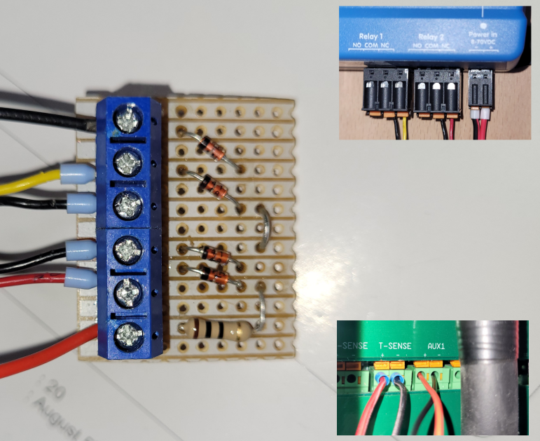
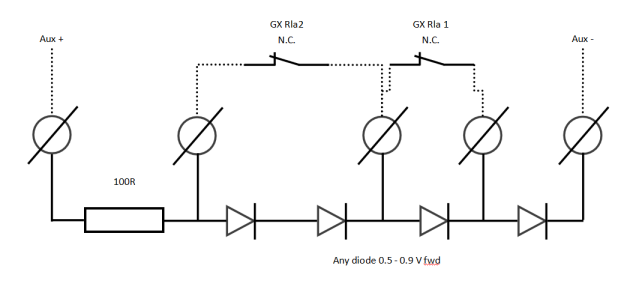
Its a simple board with 4 diodes and a current limit resistor, although the latter is not strictly necessary. The diodes are in a string with the forward voltage drop's providing a reference voltage on the Aux in terminal.
My Cerbo GX is then used to short out some diodes giving selectable charge currents, implemented by the charge control assistant.

Using the above I get 4 circa 750W steps, in my case starting at 0.
It works very well and I can now set a charge limit, including no charge, using Modbus from NodeRed to control the relays.

The flow is only for testing right now, hence the inject nodes, but it opens a load of possibilities.
In case anyone is wondering, I have set the multi to shut down the charger when 0 current is requested. This results in a Passthru, state as opposed to Bulk with 0 current, and I was a little concerned that doing this would prevent the Assisting, state from being achieved but I just put a pizza in; that's my kind of testing; and set an AC current limit of 4A.
The multi went into assisting with no issue which is just as well because the alternative was an overload trip and me looking for a TORCH!
I have to say that I am a little confused as to why a module/interface like this doesn't exist, given its simplicity and usefulness, but then I guess you could argue that charge current limiting should be available as a writable parameter in the first place.
I know this isn't a question as such, given that my pizza answered the question I originally asked, but I am posting anyway because charge current limiting/self consumption and many other related queries seem to come up all the time, and have been doing so for years.
For anyone interested in the detail...

The Aux port has a pullup, circa 600 Ohms I think, on the +, holding it at 5V if there is no current draw. The diodes/relays act as a selectable voltage reference, pulling Aux+ down to a little over the sum of Vf on all diodes that are not bypassed by a relay contact
The switching is binary, 0-3 with bit 0 on Rla1.
I know this is very simple, that is the point; I also know that there are many other ways to go, I could have used a PWM pin on the PI for example. However doing it this way means the relays can be operated via Modbus / MQTT / GX UI / VRM portal, which think is worth the minimal effort.
Additional relays could be used to force on, or off, the charger so the relay assistant could probably be made to do all sorts of stuff by modifying the output of this circuit.
Of course you can do just about anything with Node Red so I probably will not mess with the programmable relay stuff but it is worth pointing out I think.
Thoughts? could I have picked a better way? happy to learn.
