question

silverfox avatar image
silverfox asked

How to test AC Current Sensor?

After I installed the AC Current Sensor in my system, in Victron Connect VRM my Dashboard showed 'PV Inverter' with some W numbers. I assume this is the name for what the Quattro is picking up from the AC Current Sensor. After about 1 week, that PV Inverter box disappeared from my Dashboard. I re-installed the AC Current Sensor Assistant, but it still does not show up. I have two new 5k Quattro's wired 120/240 split phase, so I have the AC current sensor on L1 connected to AUX1 of the L1 Quattro.

Maybe my AC Current Sensor died? Can I test my AC Current Sensor with a multimeter or an oscilloscope or something else?

AC PV Couplingsensor
2 |3000

Up to 8 attachments (including images) can be used with a maximum of 190.8 MiB each and 286.6 MiB total.

3 Answers
Jason - UK avatar image
Jason - UK answered ·

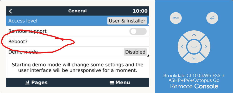
@SilverFox Im assuming you have the 40A CT sensor with the dip switches? You need to reboot the system to get it to reconnect. Mine does it every now and then, if there has been no PV generation for more than a day. It seems to thing the PV has been disconnected so it removes the PV input data on the VRM portal. After a few weeks once the system has settled down, you might find the problem goes away. I have no idea why it does it but it does settle down eventually.

1655197445216.png


1655197445216.png (70.3 KiB)
2 |3000

Up to 8 attachments (including images) can be used with a maximum of 190.8 MiB each and 286.6 MiB total.

silverfox avatar image
silverfox answered ·

@Jason - UK Thank you for that helpful information. I have what Victron calls its "AC Current Sensor" which is probably a 40A CT - here is a link: https://www.victronenergy.com/accessories/ac-current-sensor When you say a reboot, do you mean I turn the Quattro's off and then on again, thus shutting off all power for a minute, or is there some way to reboot only the needed affected area? My system is: (2) 5k Quattro's wired 120/240 split phase, 6kW Enphase PV string, DC solar modules through (2) Outback charge controllers, QH Tech LiPO4 30kW battery stack through SmartShunt, Cerbo GX, grid-tied.

1 comment
2 |3000

Up to 8 attachments (including images) can be used with a maximum of 190.8 MiB each and 286.6 MiB total.

Jason - UK avatar image Jason - UK commented ·

@SilverFox you just need to 'reboot' the GX device. If you go into the menu of the GX device, reboot the GX whilst your PV array is generating energy, when it restarts, it should pick up the signal from the current sensor and display the information in the VRM console.

0 Likes 0 ·
silverfox avatar image
silverfox answered ·

@Jason - UK It worked! The reboot was 'soft' to our system in that it did not shut off the inverters while the software rebooted. That would have been quite the hassle if it had to be done every week! When the 'PV Inverter' box re-appeared, it read 0 and the 'AC Loads' box also read 0. So I reversed the two low-voltage wires from the AC Current Sensor to the L1 Quattro and now it is reading actual numbers, and the 'AC Loads' box is too!

The watts in the 'PV Inverter' box is close to 1/2 the expected value. We have two Quattro's, wired split-phase 12/240, and only 1 current sensor, so I guess that makes sense. I wonder if that is how other split-phase setups work out for other users? Maybe there is an easy way in the software to double the voltage readout? I'm not going to put in a second AC Current Sensor (on L2) just to make the numbers 'look right.'

In the USA, by far the most common residential wiring is 120/240 split-phase, 60 Hz.

Thanks again!

2 |3000

Up to 8 attachments (including images) can be used with a maximum of 190.8 MiB each and 286.6 MiB total.