From reading the manual, the Lynx Smart BMS combined with a CerboGX does not seem to need battery protect as it performs that function itself, yet all the circuit diagrams I can find seem to still include battery protect.
Can anyone explain?
This site is now in read-only archive mode. Please move all discussion, and create a new account at the new Victron Community site.
From reading the manual, the Lynx Smart BMS combined with a CerboGX does not seem to need battery protect as it performs that function itself, yet all the circuit diagrams I can find seem to still include battery protect.
Can anyone explain?
Hi @Sweyn,
Can you please link to those circuit diagrams?
In general, there would be no need for a BatteryProtect in a system with Lynx Smart BMS. The contactor in the BMS should be seen as a fallback (or secondary) safety system, if for example ATC/ATD fail to disable loads or chargers.
Every system is different and so are the circumstances that lead to the installation of further safety measures, for example with a BatteryProtect.
There may be good reasons to add a BatteryProtect, for example if you want to control individual chargers (especially those that are not DVCC compatible or missing a remote on/off port and thus not controlled by the BMS and the GX device) or individual load circuits, you can certainly do this with a BatteryProtect.
In addition, a BatteryProtect switches off at a voltage to be defined and switches on again at another voltage. The Lynx Smart BMS does not do this. It only (unless you switch it in Off or Standby mode) opens the contactor when the battery reports an alarm state (eg low cell voltage) in order to protect the battery from further discharge.
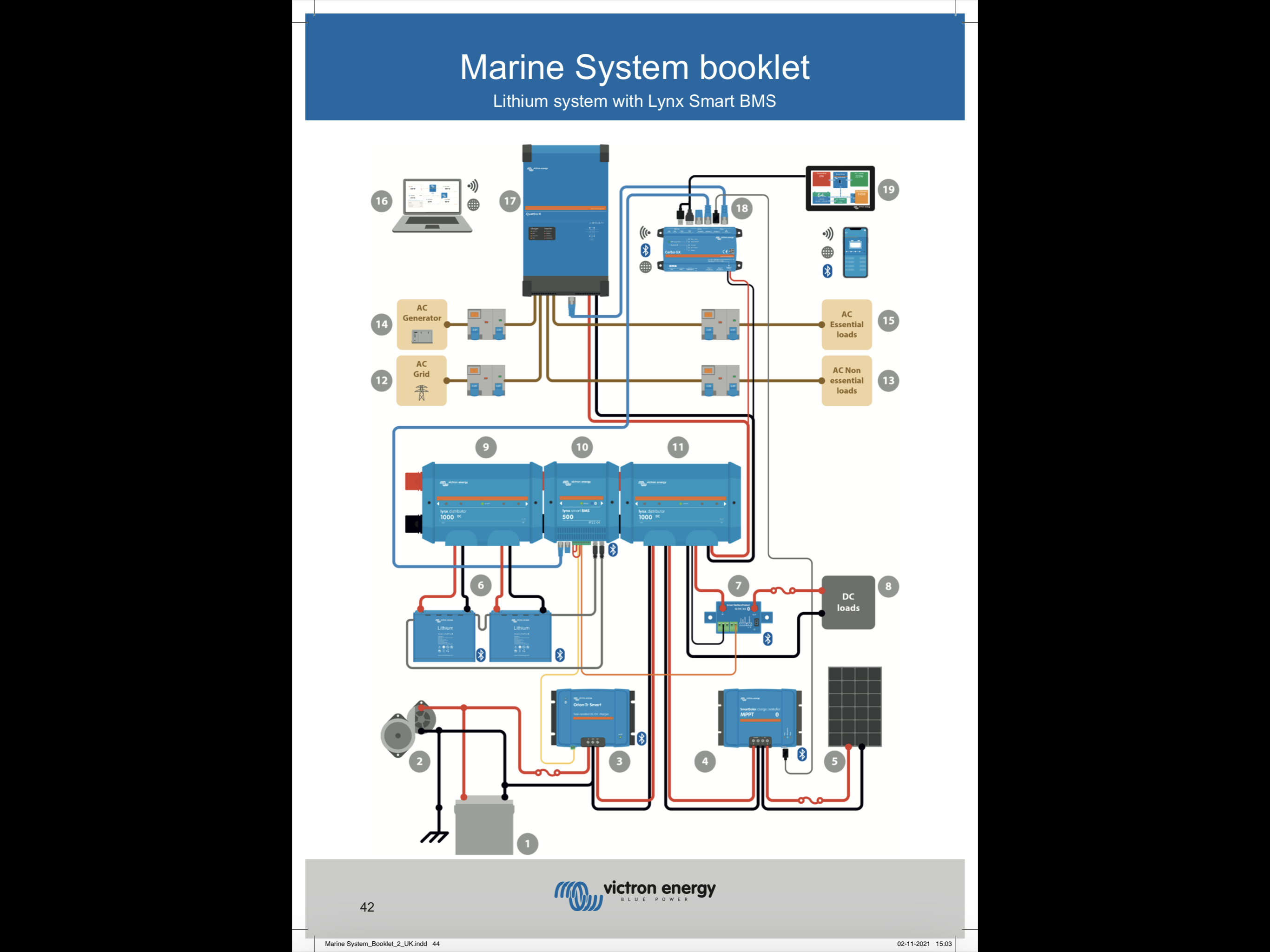
 This from the marine system booklet.
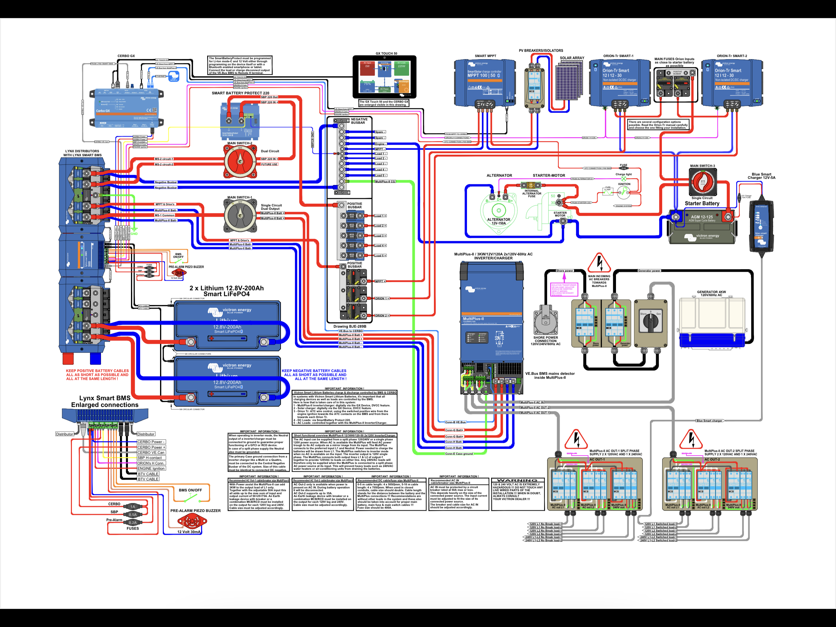
 Or this one from victron
Victron BatteryProtect product page
Victron VE.Bus BMS product page
Victron 3rd party BMS compatibility page
Lynx Shunt VE Can online manual
Additional resources still need to be added for this topic
33 People are following this question.