question

mvader (Victron Energy) avatar image
mvader (Victron Energy) asked

Venus OS v2.90~8 available for testing

UPDATE MAY 29th: meanwhile we released v2.90~10. I’ll update the documentation asap. ~10 fixes several recent regressions, including remote firmware update hanging during device scan.


Hi,

Rather short, I’ll expand this later.

Previous post: https://community.victronenergy.com/questions/133780/venus-os-v2905-available-for-testing.html


Changes since then:

- add wakespeed support (monitoring). Requires wakespeed firmware which is not available yet! I’ll post the details of that once available. Should be within a few weeks.

- Improve Bluetooth sensor menu & options (continuous scanning, see all inserted adapters, and more)

- improve bluetooth radio on Cerbo Gx stability: if it malfunctions due to over temperature, the chances of it restarting when cooled down are now higher. But rest stays and will always remain the same for current hardware version: for any serious use, insert a usb bluetooth adapter as per manual.

- gx lte & gx gsm: Add modem username/password settings, required by some providers

- various EV Charger improvements (menu, connection stability, VRM)

- Fix the sign of the current and power for DC meters that are configured as source (except fuel cell and alternator, which were correct). broken since venus v2.80~18

- Add missing "Inverter only" mode to mobile overview

- Add support for VE.Bus BMS v2 firmware updates

- Venus OS Large: fix Node-RED Dashboard button missing on VRM and fix image selection / check for update function in online update menu.

Venus OS
2 |3000

Up to 8 attachments (including images) can be used with a maximum of 190.8 MiB each and 286.6 MiB total.

14 Answers
Kevin Windrem avatar image
Kevin Windrem answered ·

Documentation only: dbus services are not listed for alternator, fuel cell, DC source DC system here:

https://github.com/victronenergy/venus/wiki/dbus

(posted here because v2.90~8 adds Wakespeed support)

6 comments
2 |3000

Up to 8 attachments (including images) can be used with a maximum of 190.8 MiB each and 286.6 MiB total.

bathnm avatar image bathnm commented ·

@Kevin Windrem what is missing?

alternator, dcsource

fuelcell

dcsystem

dcload

All define the various paths available for alternator, fuel cell, DC source DC system

0 Likes 0 ·
Kevin Windrem avatar image Kevin Windrem bathnm commented ·
The paths are there but not the service: com.victronenergy. ???????
0 Likes 0 ·
bathnm avatar image bathnm Kevin Windrem commented ·

@Kevin Windrem I see what you mean.

alternator is com.victronenmergy.alternator

dcload is com.victronenmergy.dcload

dcsource is com.victronenergy.dcsource

dcsystem is com.victronenergy.dcsystem

fuelcell is com.victronenergy.fuelcell


0 Likes 0 ·
mvader (Victron Energy) avatar image mvader (Victron Energy) ♦♦ bathnm commented ·
added, thanks.
0 Likes 0 ·
Kevin Windrem avatar image Kevin Windrem commented ·
Also don't see any Power parameters in the documentation. Are they there or does it need to be calculated from voltage and current?

I'm interested in the power to the DC bus (battery, etc).

0 Likes 0 ·
mvader (Victron Energy) avatar image mvader (Victron Energy) ♦♦ Kevin Windrem commented ·
Hi @Kevin Windrem , needs to be calculated.
0 Likes 0 ·
bathnm avatar image
bathnm answered ·

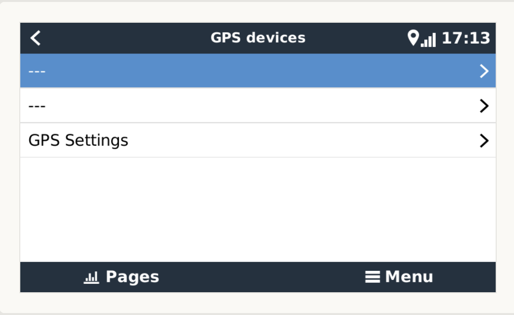
Has anyone else got an issue that the list of GPS is ---?

1652544802889.png


1652544802889.png (47.1 KiB)
5 comments
2 |3000

Up to 8 attachments (including images) can be used with a maximum of 190.8 MiB each and 286.6 MiB total.

johnny-brusevold avatar image johnny-brusevold commented ·

@Bathnm

Yes, the same graphic error here. GPS works fine

0 Likes 0 ·
Sarah avatar image Sarah commented ·

Same error.

0 Likes 0 ·
philippe avatar image philippe commented ·
Yes same error
0 Likes 0 ·
mvader (Victron Energy) avatar image mvader (Victron Energy) ♦♦ philippe commented ·
Fixed in v2.90~10 @Bathnm . Pls let me know if its not.
0 Likes 0 ·
bathnm avatar image bathnm mvader (Victron Energy) ♦♦ commented ·

@mvader (Victron Energy) I can confirm it is fixed.

0 Likes 0 ·
Justin Tierney avatar image
Justin Tierney answered ·

The firmware update under the device lost doesn’t seem to be working. If I back level to 2.90 ~5 it works without issue.

4 comments
2 |3000

Up to 8 attachments (including images) can be used with a maximum of 190.8 MiB each and 286.6 MiB total.

Kevin Windrem avatar image Kevin Windrem commented ·
I am not seeing any issues. It now even shows a Large update of the same version!!


What specific problem are you seeing?

0 Likes 0 ·
Justin Tierney avatar image Justin Tierney Kevin Windrem commented ·
Keeps hanging when scanning ve devices and never returns anything. However, looks like someone just posted about this in the Q&A forum as well so might not be a 2.90 ~8 bug.
0 Likes 0 ·
mvader (Victron Energy) avatar image mvader (Victron Energy) ♦♦ Justin Tierney commented ·

Fixed in v2.90~10. And thank you for reporting!

0 Likes 0 ·
Sarah avatar image Sarah commented ·
Same error.
0 Likes 0 ·
Justin Tierney avatar image
Justin Tierney answered ·

e9ea1c90-1e6a-4efb-b3a6-a3843a763aeb.png

Screenshot


3 comments
2 |3000

Up to 8 attachments (including images) can be used with a maximum of 190.8 MiB each and 286.6 MiB total.

Kevin Windrem avatar image Kevin Windrem commented ·
Oh, sorry. I thought you were referring to the GX device's GUI, not VictronConnect.
0 Likes 0 ·
Justin Tierney avatar image Justin Tierney Kevin Windrem commented ·
No worries. It’s via the devices list on the left side in vrm if that makes a difference.
0 Likes 0 ·
mvader (Victron Energy) avatar image mvader (Victron Energy) ♦♦ Justin Tierney commented ·
Fixed in v2.90~10
0 Likes 0 ·
thomasw-1 avatar image
thomasw-1 answered ·

Hi Matthijs @mvader (Victron Energy) ,

I have seen that in v2.90~5 also some modification on DVCC have been applied.
However it still seems that that "DVCC charge limit" is still not working for a mixed inverter/MPPT environment (see comment details in https://community.victronenergy.com/questions/120577/venus-os-v2831-available-for-testing.html).

Do you have any plans, when a potential fix might be scheduled?


1 comment
2 |3000

Up to 8 attachments (including images) can be used with a maximum of 190.8 MiB each and 286.6 MiB total.

mvader (Victron Energy) avatar image mvader (Victron Energy) ♦♦ commented ·
No, sorry.
0 Likes 0 ·
sportswagoneer avatar image
sportswagoneer answered ·

The MFD/HTML5 app stopped working for me. Now showing only a white screen when I choose the Victron app. (B&G)
The NMEA2000 connection is working, showing SOC.
First use of the season - so could be broken in earlier upgrade. No changes in ethernet structure or GX settings (both MQTT settings enabled and all three batteries set to “visible”.)

17 comments
2 |3000

Up to 8 attachments (including images) can be used with a maximum of 190.8 MiB each and 286.6 MiB total.

mvader (Victron Energy) avatar image mvader (Victron Energy) ♦♦ commented ·
Hi @Sportswagoneer , is this still happening for you with v2.90~10? If it does, pls let me know which type of B&G you have.

Thank you for the report!

0 Likes 0 ·
sportswagoneer avatar image sportswagoneer mvader (Victron Energy) ♦♦ commented ·
Yes. Used 2.90~10 all weekend - and only a white screen on the MFD even if the app icon shows as usual.

Using a Zeus2 12” connected (wired) through their Wifi-1 module. Both the Zeus and the Cerbo GX are wired to a Teltonika 4g router (RUT240) also with the latest firmware. I can see the marine app from the Cerbo with no problem on an iPad in the same LAN at the venus.local/app/ address. So it would seem that the MFD is unable to locate the html5 page…
Tried to look into the whole “Link-local” stuff - but had a hard time reading up on it. The Cerbo shows a “Link-Local“ address but I can’t find a way to check that on the MFD. The router is set to bridge the two wired interfaces - so I believe they should be able to connect even without it (using the router as just a switch…)

0 Likes 0 ·
mvader (Victron Energy) avatar image mvader (Victron Energy) ♦♦ sportswagoneer commented ·
Hi, thank you for the quick reply. Is it OK if we login remotely to the system to check the logs? For that, it needs to be on the internet, and Settings -> General -> Remote Support must be enabled. Installation Neste Sommer 2, right?
0 Likes 0 ·
sportswagoneer avatar image sportswagoneer mvader (Victron Energy) ♦♦ commented ·
Yes please do. The Cerbo is on-line. (The MFD is not active now though.)
0 Likes 0 ·
Show more comments
kurtinge avatar image kurtinge sportswagoneer commented ·
Are you sure you have the Seus2 12" ? I also have this MFD, but this model never had support for the HTML5-app as far as I experienced. My MFD is connected to a generic router directly and my Venus is also connected to the same router. I never saw any Victron app


0 Likes 0 ·
sportswagoneer avatar image sportswagoneer kurtinge commented ·

Yes - I’m positive it’s a Zeus2. Note that I’m also using the “Go free Wifi-1” module and that I have a wired Ethernet connection from both the MFD (through the Wif-1) and the Cerbo GX to the router.

0 Likes 0 ·
Show more comments
slapperia avatar image
slapperia answered ·

Hi. My MDF`s are working (Raymarine Axiom)

Same graphic issue with GPS. GPS is working.

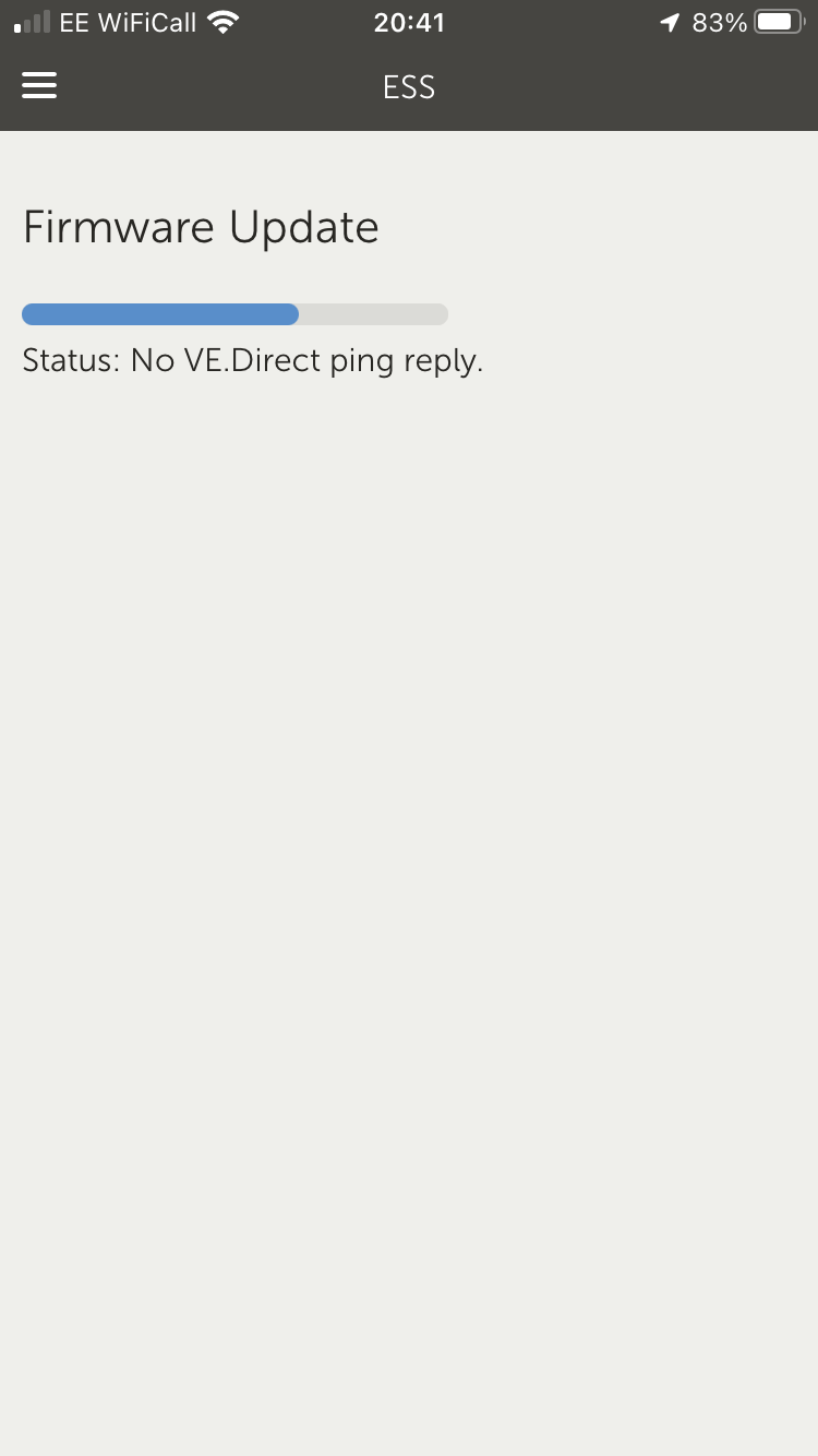
I get the same issue when try to update firmware:

Status: No VE.Direct ping reply.

1 comment
2 |3000

Up to 8 attachments (including images) can be used with a maximum of 190.8 MiB each and 286.6 MiB total.

mvader (Victron Energy) avatar image mvader (Victron Energy) ♦♦ commented ·
Hi all solved, thank you for the reports!
0 Likes 0 ·
gregoryx avatar image
gregoryx answered ·

I hope I'm not the only one experiencing this... I hate to find out if I've just made some dumb mistake.

Cerbo GX.

Back on 2.82-ish, Ruuvi tags worked great. 2.85-ish they disappeared. Went back on betas to see if they'd come back - 2.90~2 then 2.90~5 then 2.90~6 then 2.90~8. Read all the "BT has issues" stuff I found and ordered one of the "approved" units from the green-post list. Plugged it in and still same problem. And not sure if there's something I should be doing to switch over to it.

I moved to the Large image at one point to test NodeRed. But in hopes of getting the Ruuvi units back, I'm currently back on normal image. I've gotten better at pulling down updates from command line to try everything I can... but no luck. Rolled back to 2.82, then 2.85 then back to 2.90~8.

On 2.90~8 now and there's no Bluetooth in the I/O menu any more. Roll back to 2.82 and it's there but no Ruuvi units show up.

Suggestions?

2 comments
2 |3000

Up to 8 attachments (including images) can be used with a maximum of 190.8 MiB each and 286.6 MiB total.

mvader (Victron Energy) avatar image mvader (Victron Energy) ♦♦ commented ·
Hi @gregoryx , what we did in a recent version is hide the menu in case there is no working bluetooth adapter. So for a Cerbo what could happen there, with only the built-in bluetooth, is: when Cerbo is cold its visible, Cerbo heats up, bluetooth fails, menu disappears. And then if you let the Cerbo cool down it comes back again.


Is it working well for you in the meantime? If not, please try a recent version (v2.90~10), and then post a post a picture of the menu page that lists the inserted bluetooth adapters.

0 Likes 0 ·
gregoryx avatar image gregoryx mvader (Victron Energy) ♦♦ commented ·
Well... at least that makes sense! The temps would explain some of the times of day it goes on/off.


I'm on 2.90~10 right now and seeing the same thing. And I'm seeing the same thing - no BT menu - with the internal BT disabled and an external dongle in use. (Disabled the internal in one of those windows where it was showing up.)


So... with what you describe, I'd expect the external dongle to show up at least? And I've tried two different dongles - that both work when it works.


0 Likes 0 ·
Mark avatar image
Mark answered ·

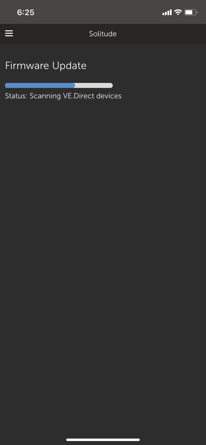
3e915bb8-93ce-44af-8317-f112ae099bfc.pngCan’t access remote firmware update,revert back to 2.85 all works ok!

3 comments
2 |3000

Up to 8 attachments (including images) can be used with a maximum of 190.8 MiB each and 286.6 MiB total.

David avatar image David commented ·
Same issue here
0 Likes 0 ·
Sarah avatar image Sarah David commented ·

I believe this has been resolved in the latest update. V2.90~10.

0 Likes 0 ·
mvader (Victron Energy) avatar image mvader (Victron Energy) ♦♦ Sarah commented ·
Indeed, thanks! solved in v2.90~10
0 Likes 0 ·
philippe avatar image
philippe answered ·

A bug?
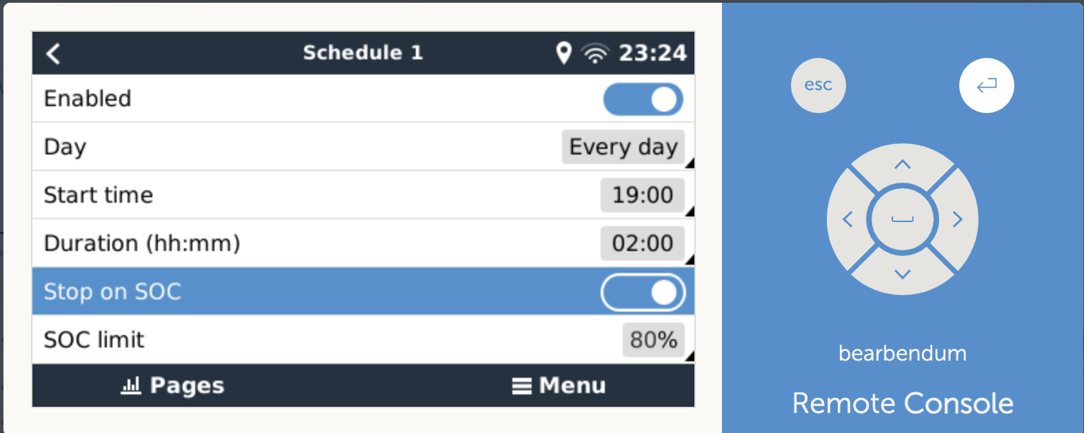
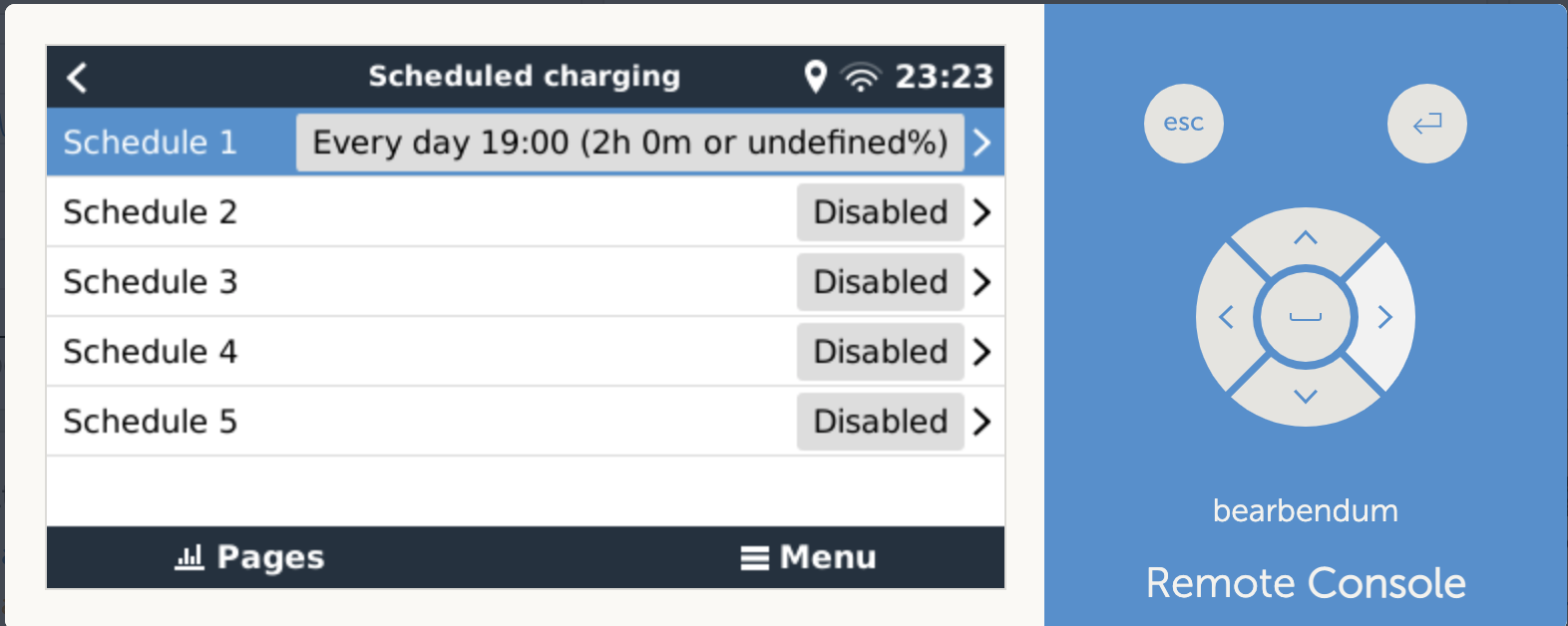
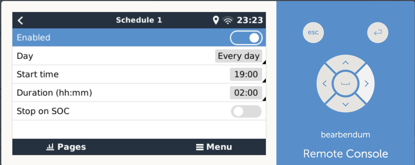
ESS > Scheduled Charging > Schedule 1 : display "..or undefined %" in stead of the SOC value.

Stop on SOC is grayed out. When I but it back on 80%, it does not change the % in the display and the parameter SOC is again off.screenshot-2022-05-16-at-232323.pngscreenshot-2022-05-16-at-232351.pngscreenshot-2022-05-16-at-232437.png


2 comments
2 |3000

Up to 8 attachments (including images) can be used with a maximum of 190.8 MiB each and 286.6 MiB total.

pau1phi11ips avatar image pau1phi11ips commented ·

It's been raised on Github https://github.com/victronenergy/venus/issues/942

0 Likes 0 ·
mvader (Victron Energy) avatar image mvader (Victron Energy) ♦♦ pau1phi11ips commented ·
Hi, yes, and solved. Thanks!
0 Likes 0 ·
nebulight avatar image
nebulight answered ·

Wow, wakespeed support! Can't wait to see this!

2 |3000

Up to 8 attachments (including images) can be used with a maximum of 190.8 MiB each and 286.6 MiB total.

hjohnson avatar image
hjohnson answered ·

Can confirm that, even with firmware 2.4.3 on my WS500, the wakespeed now shows up in Venus and I am getting (some) data off of it.

Now to figure out why it doesn't actually seem to be driving the alternator.

Unrelated, in my setup the Cerbo does not seem to be pushing the info for my starter battery (on a BMV712 connected via VE.Direct as a separate NMEA2000 battery. Battery 1 appears to be my house battery, battery unit 2 looks to be the PV voltage off of my MPPT.

3 comments
2 |3000

Up to 8 attachments (including images) can be used with a maximum of 190.8 MiB each and 286.6 MiB total.

pwfarnell avatar image pwfarnell commented ·
I thought that this implementation was monitoring only, i.e. only reading info from the WS500. To drive the alternator do you not need the Lynx Smart BMS.
0 Likes 0 ·
hjohnson avatar image hjohnson pwfarnell commented ·

@pwfarnell

I wasn’t very clear on my “it” in my post. :) It was why the WS500 wasn’t driving the alternator. It was a configuration issue, owing to the tach input not working reliably with my alternator. It’s a big alternator on a tiny engine, so I didn’t want to load the engine until 1100rpm, but the tach input was reading low values (say 100rpm), so never actually pushing any field into the alternator.

0 Likes 0 ·
mvader (Victron Energy) avatar image mvader (Victron Energy) ♦♦ hjohnson commented ·
Field % will become visible on GX device as well as over VRM.
0 Likes 0 ·
thomasw-1 avatar image
thomasw-1 answered ·

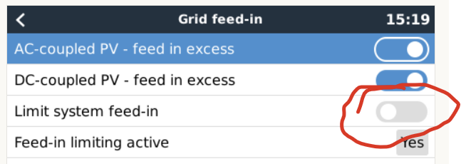
Bug in "limit system feed-in" in OS v2.90~10.

That version shows a weird behaviour of "limit system feed-in":

  • In case the button is set to "activated", you return to the ESS menu and navigate back into "Grid feed-in", the option is shown as "not activated"
  • In case the menu item "Limit System feed-in" gets deactivated, ESS does limit feed-in power still with previously set "power limit" instead of using unlimited power.

1653311950626.png


1653311950626.png (41.2 KiB)
4 comments
2 |3000

Up to 8 attachments (including images) can be used with a maximum of 190.8 MiB each and 286.6 MiB total.

elvis avatar image elvis commented ·

I too am experiencing this

https://community.victronenergy.com/questions/137072/limit-feed-in-not-checked-but-feed-in-is-limited.html


0 Likes 0 ·
thomasw-1 avatar image thomasw-1 elvis commented ·
Thanks for confirming my observation Elvis!
0 Likes 0 ·
daniel avatar image daniel thomasw-1 commented ·

I discovered the same problem, Izak from L3 victron support already knows about the problem.

0 Likes 0 ·
Paul Test avatar image Paul Test daniel commented ·
Same here at 2.90.10
0 Likes 0 ·
aegir avatar image
aegir answered ·

"add wakespeed support (monitoring). Requires wakespeed firmware which is not available yet! I’ll post the details of that once available. Should be within a few weeks."


Any details on this? will you be able to see charge rate, voltages, temps etc. data from the wakespeed regulator?

11 comments
2 |3000

Up to 8 attachments (including images) can be used with a maximum of 190.8 MiB each and 286.6 MiB total.

bathnm avatar image bathnm commented ·

Aegis, Good morning. There is not a simple answer. There are many complexities which are still being documented. As the WS500 is very flexible and can use sensors in a flexible way depending on how it is configured. Here are some of the key details an installer must consider when setting this up.

  • The WS500 must be connected to the VE.Can port. It will not work with the BMS.Can port. If you therefore have a CAN connected battery on the BMS.Can then the WS500 will be connected to that and at this stage not supported
  • To get alternator current (and therefore power) a shunt must be installed on the positive output of the alternator and connected to the WS500. The WS500 must then be configured with shunt at battery set to 0 via $CCN configuration line. The shunt ration must also be set correctly via the $SCA configuration line
  • To report correct engine RPM, the alternator/engine pulley ration must be set via the $SCT configuration line
  • The reported alternator voltage is pulled from the alternator positive feed (red wire in the alternator portion of the loom). If this is connected at the battery, you ill get battery voltage and not alternator output. If connected to the alternator positive post you will get true alternator voltage. If you have a 48v alternator driven by a 12v field, you will get the field voltage, aka 12v)
  • You need to ensure that the feature in wire, is connected to the ATC signal of the BMS
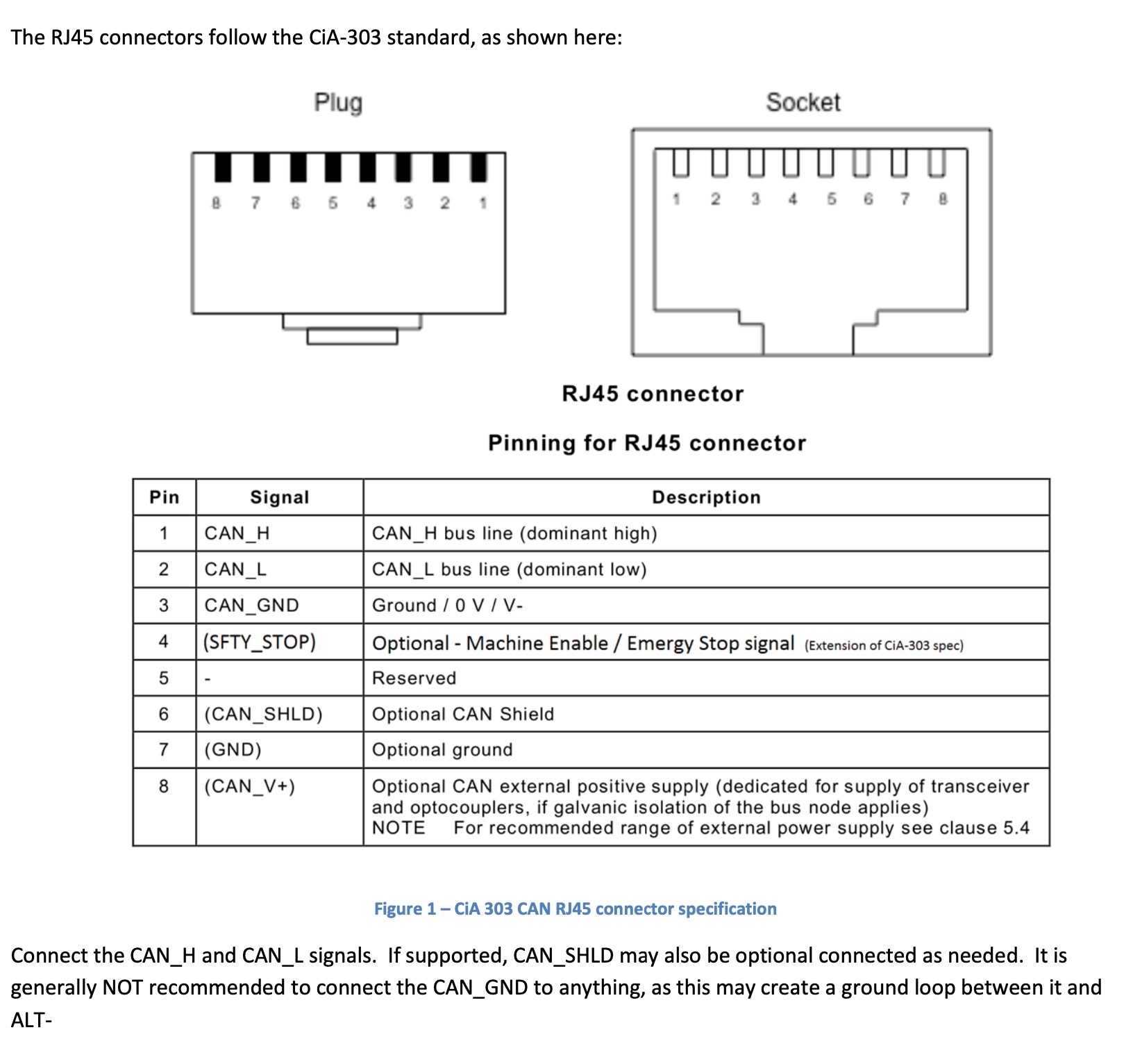
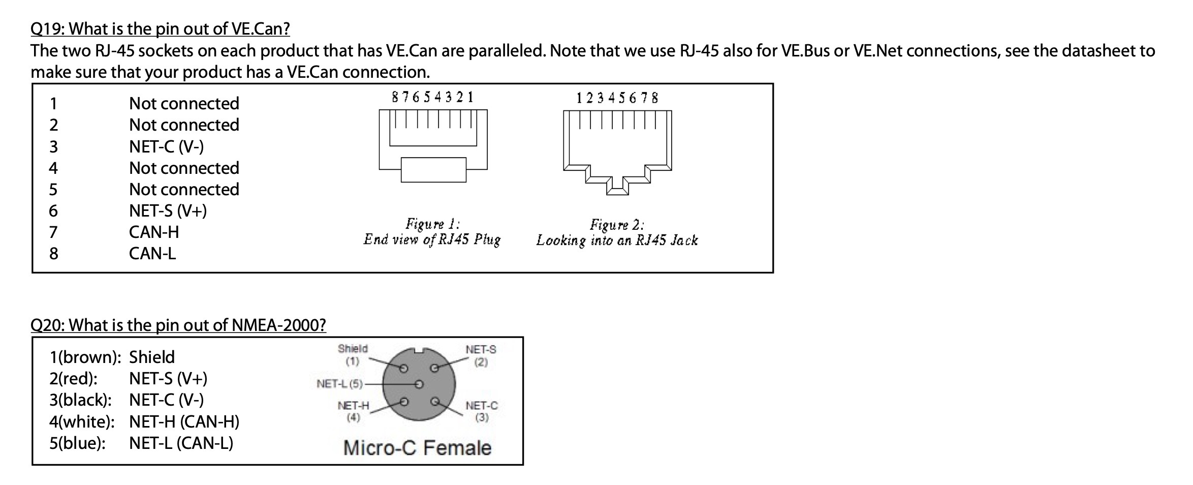
  • The VE.Can and WS500 Can ports have different pin outs, so you need to make a cable or purchase a cable from Wakespeed

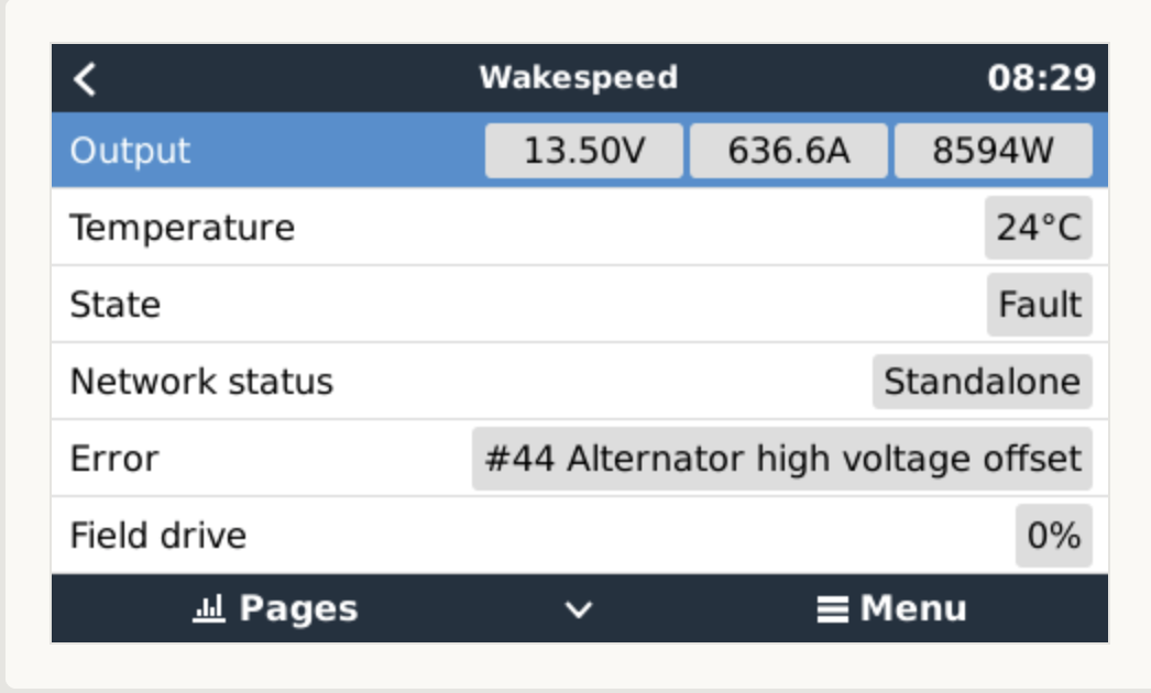
The system will report, voltage, current, power, charge mode, network status, field drive, alternator temperature, engine RPM, alternator RPM. Any error messages and warnings that the WS500 might be in. So if it looses CAN connection with the BMS it will report this.

The Wakespeed beta will be available real soon.

I have also attached a screen shot, and no I was not generating 600A+ from an alternator, it is on a test bed with a dummy shunt.

1653466590234.jpeg1653466596671.jpeg

1653467355551.png

0 Likes 0 ·
1653466590234.jpeg (278.4 KiB)
1653466596671.jpeg (231.4 KiB)
1653467355551.png (97.5 KiB)
nebulight avatar image nebulight bathnm commented ·
This looks AWESOME! Hopefully Victron can get this data into VRM and maybe even on the home power flow screen.
0 Likes 0 ·
bathnm avatar image bathnm nebulight commented ·

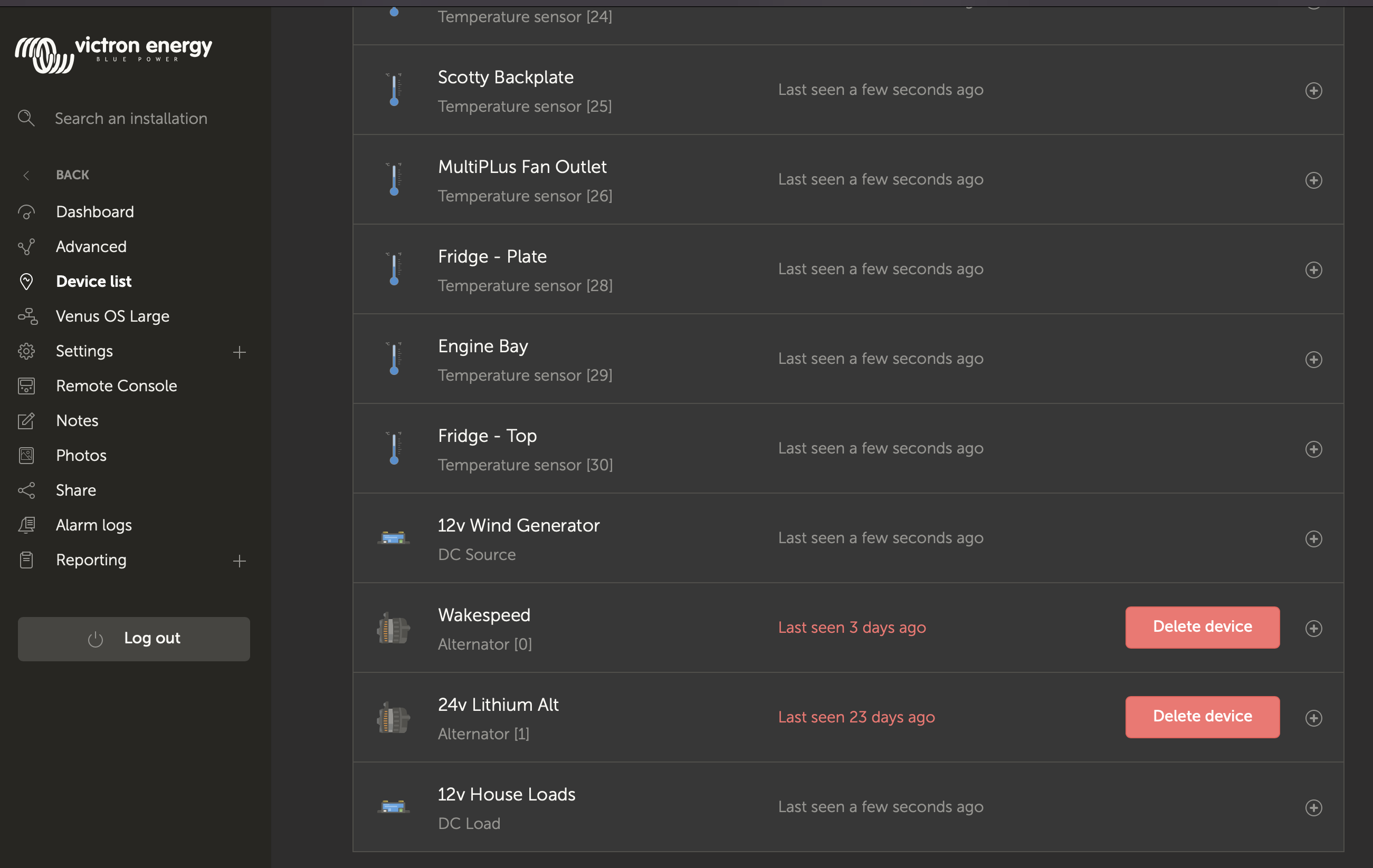
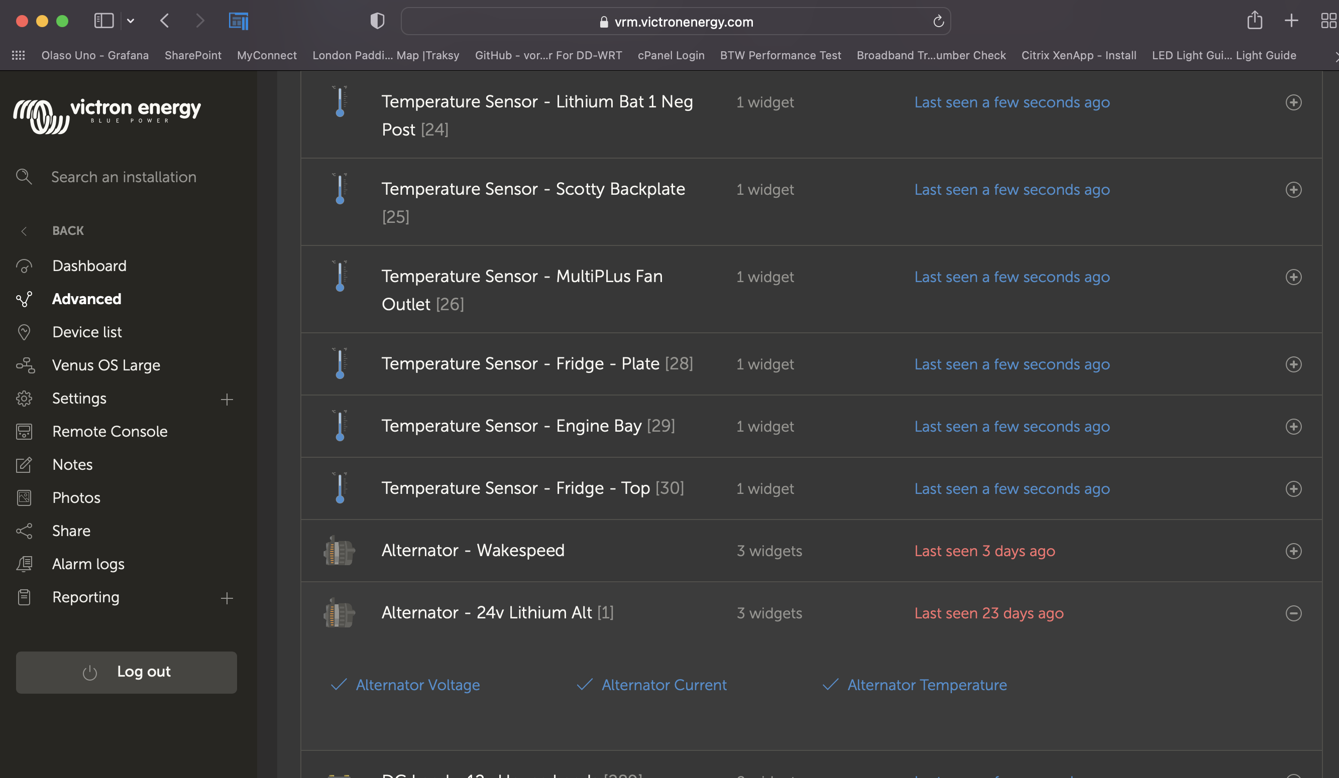
It's coming.. Already in the device list and able to graph in Advanced the Voltage, Current and Temp. I am sure other data may follow at some stage.screenshot-2022-05-25-at-185326.pngscreenshot-2022-05-25-at-185457.png

0 Likes 0 ·
nebulight avatar image nebulight bathnm commented ·

Wow. Can't wait for a GA release of this new firmware!

0 Likes 0 ·
pwfarnell avatar image pwfarnell bathnm commented ·
It would be great if the Cerbo GX could send battery current and temperature to the WS500 if it was available.
0 Likes 0 ·
stevomyatt avatar image stevomyatt bathnm commented ·

Thanks for the info @Bathnm.


I have a question about the current reported from the WS500 when a plain shunt is installed exclusively on the alternator and signal wired to the WS500 (second bullet point you described).


Can this current be used in the in the "DC System" calculation, along with SmartShunts configured as DC Meters?


If so, there will be no need to install both a plain shunt for the WS500 and a SmartShunt for the Cerbo.


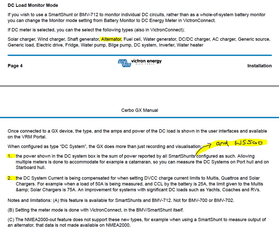
ws500-dc-load-monitor-mode.jpg

0 Likes 0 ·
bathnm avatar image bathnm stevomyatt commented ·

@stevomyatt A great question.

The VenusOS treats current information coming from either a Smart Shunt (configured in DC monitor mode set to Alternator) or the WS500 in the same way regardless of source.

So your re correct, both are not needed.

For others coming to this at a later date a few things to consider regarding which approach to take.

  • A SmartShunt can not be inserted in the positive line from the alternator, therefore must go in the negative. A lot of alternators are case grounded, and therefore have their negative shared with the engine, and thus the SmartShunt would be on the negative connecting to the engine block. Not great as you will pick up other current loads and sources, possibly even from a second alternator (such as a stock alternator). Therefore are you truly measuring alternator current?
  • If you deploy both the Wakespeed 500 minus it's shunt capability and a Smart Shunt, you would have one device in the VenusOS reporting details about the alternator, such as voltage, engine RPM, alternator RPM, charge mode, etc and a second SmartShunt device reporting just alternator current.
  • Having a Wakespeed 500 with its shunt capability and a Smart Shunt reporting on output of an alternator, will cause double counting of current.

It becomes a design decision regarding how you want the entire system to work and operate. If you have a Wakespeed 500 then the design decision should be to have that report about the alternator as a single device, therefore including a plain old shunt connected to the WS500.

If you do not have a WS500 and the alternator is isolated with it's own negative, then a SmartShunt makes sense, but with less information being available in the UI.

0 Likes 0 ·
pwfarnell avatar image pwfarnell bathnm commented ·
But if you are using the shunt on the battery (say a BMV 702) to provide the battery charge amps for the WS500 to change from absorption to float you can not report the alternator amps to the Cerbo GX so you need the Smartshunt to provide the alternator amps separately as a DC energy meter unless you forgo swapping from absorption to float using tail current. This is for an install with AGM batteries, not lithium so no BMS integration to derive the battery amps from e.g. a Lynx BMS. This is why forwarding the battery amps from the Cerbo GX would be a goal to aim for.
0 Likes 0 ·
bathnm avatar image bathnm pwfarnell commented ·
@pwfarnell. You have highlighted that there is never a simple answer to these question. In your install with no other means of supplying tail current and wanting it for the transition from but to absorption then yes you need the WS500 shunt connected to the battery. You then forgo reporting alternator current. You must be lucky with an alternator that is not case grounded to be able to use a smart shunt configured as a DC Monitor to collect the alternator current.


You could always have the Cerbo send the battery voltage and current over the N2K network and have the Wakespeed utilise the N2K battery details for the tail current. Then the shunt an be put at the alternator. Saves you a smart shunt, but requires a dumb shunt and an N2K/VE.Can cable. This could give you a more integrated solution.

So really depends on what you would like to achieve.

0 Likes 0 ·
pwfarnell avatar image pwfarnell bathnm commented ·

The output of battery current and temperature from the Cerbo GX to the WS500 via NMEA2000 would be an interesting solution. Without an NMEA2000 network is it as simple as connecting the Cerbo GX and WS500 with the cross over CAN cable (plus terminators), setting the WS500 to receive battery current and temperature via NMEA2000 RAT ($CCN: Enable_ALT_CAN = 1) and then setting the Cerbo GX VE.can.port NMEA2000-out option to on. Battery temperature is connected to the Cerbo GX not the BMV and shared on DVCC.

0 Likes 0 ·
stevomyatt avatar image stevomyatt bathnm commented ·

Thanks @Bathnm, that's great.

0 Likes 0 ·

Related Resources