question

ohiobrits1 avatar image
ohiobrits1 asked

MultiPlus 12/3000/120-50 120V inrush current on initial startup

What is the approximate inrush current for the 12/3000 MultiPlus when first connected (or reconnected) to a DC supply after a full discharge of the onboard capacitors? I'm specifying a contactor to isolate the MultiPlus completely from the battery and need to be sure I won't suffer from contact welding issues.

The contactor is being installed to ensure the approx 200mA drain from the MultiPlus with inverter disabled (via an assistant) does not continue to drain the battery. As a secondary but related question, is there a way to turn the MultiPlus fully off via an assistant or other software means? This would negate the need for a contactor and would be preferable.

The Contactors I am looking at have suggested max 500A limit for make to avoid welding issues but are rated for 500A+ in closed state so should be more that adequate for any steady state load.

MultiPlus Quattro Inverter Charger
2 comments
2 |3000

Up to 8 attachments (including images) can be used with a maximum of 190.8 MiB each and 286.6 MiB total.

mihair avatar image mihair commented ·

Hi,


There is only one valid solution to limit inrush current on coupling battery to Multi trough DC contactor

1. Prior to coupling the contactor you should put in parallel to DC contactor poles a 20-30 ohm 10W power resistor via a small serial power relay

2. After 5...10 seconds the contactor can be engaged and then the small relay disengaged

All that logic can be implemented using a small ATMEL or Microchip microprocessor or can be designed using NE555 and few additional components :-)


KR,

Mihai

0 Likes 0 ·
Show more comments
7 Answers
kai avatar image
kai answered ·

I would conservatively assume that with caps at zero voltage that they're literally dead shorts (likely to be a bank of low ESR electrolytics). The inrush current is then limited by the battery internal resistance and the cable loop resistance. Should be able to get a ball park estimate from your system design.

Look into sequencing a pre-charge if the above numbers are not to your liking.

I ran into the same issue with the quiescent draw in my design. I now use the highly technical mitigation of leaving the switch in the off position when not in use.

Multiplus 2 has lower quiescent but its only 48v at present.

4 comments
2 |3000

Up to 8 attachments (including images) can be used with a maximum of 190.8 MiB each and 286.6 MiB total.

ohiobrits1 avatar image ohiobrits1 commented ·

kai - thanks. I can take a look at the calculation and get a ballpark number as you suggest. I am seeing what I think is a sticking contactor in my test setup so I suspect there is definitely an issue with high in-rush.

FYI - the only way I found to "turn off" the Multi is to simulate unplugging the VE.Bus cable by disconnecting 4 of the 8 VE.Bus wires and also pull out the remote switch jumper that is installed from the factory. This was tested manually with a spliced ethernet cable disconnecting one wire at a time to view the effect but could be done via low power relays or other means for an automatic workaround. Not an elegant solution and with its own small power needs for relay coils during operation but workable.

The Victron VE.Bus BMS apparenrty does turn off the MultiPlus on low cell voltage. I assume this is done over the bus but I could not find any mention of a turn off code in the communication documents.

0 Likes 0 ·
kai avatar image kai ♦ ohiobrits1 commented ·

The contactor you're looking at will also continuously draw power for its coil, unless you're planning on using a magnetically latched version?

0 Likes 0 ·
tilo avatar image tilo commented ·

As Kai said, the inrush current depends also on the specifics of your installation. That means there is no accurate answer that is valid for all cases. I think the only precise way to find out is to measure with an oscilloscope the inrush peak current in your installation. Maybe you can borrow an oscilloscope?

0 Likes 0 ·
Pat Davitt avatar image Pat Davitt commented ·

May be easier to find a multimeter that measures inrush current. I have an AC/DC Clamp multimeter (Fluke 376 FC) that has an inrush measurement function. Just clamp it around the positive wire and then turn on the power to the Multiplus. It measures and stores the inrush amperage and then gives you the steady state reading.

Pat

0 Likes 0 ·
boekel avatar image
boekel answered ·

Any contactor will die if you don't use a pre-charge device.

I'm using a manual switch in my test-setup with a 25ohm resistor to charge the inverters before turning on the breaker, another trick is to supply the inverter with AC so it starts as a power supply and charges the capacitors for you.

I don't know the current draw during different 'off' states.

2 comments
2 |3000

Up to 8 attachments (including images) can be used with a maximum of 190.8 MiB each and 286.6 MiB total.

ohiobrits1 avatar image ohiobrits1 commented ·

Boekel, thanks for the input. I have been investigating a pre-charge solution also which is recommended by the contactor manufacturer when switching circuits that have capacitors.

What is the power rating of your resistor?

0 Likes 0 ·
boekel avatar image boekel ♦ ohiobrits1 commented ·

I use anything I have available, 20-100W

0 Likes 0 ·
Pat Davitt avatar image
Pat Davitt answered ·

This is a question, not an answer. If the Multiplus turned off, either by the rocker switch on the Multiplus, a Venus device, or a wired remote On-Off-Charger Only switch. And then you turn off the power, through a contactor, to the Multiplus.

When you then, through the contactor, turn on the power to the Multiplus, do the capacitors charge, or do they wait until the Multiplus is turned on?

I don't know, but I would like to.

Pat

2 comments
2 |3000

Up to 8 attachments (including images) can be used with a maximum of 190.8 MiB each and 286.6 MiB total.

kai avatar image kai ♦ commented ·

The capacitors are directly connected to the DC bus input. The charging via the DC bus input occurs regardless of the multiplus state (on/off/partially on).

1 Like 1 ·
Pat Davitt avatar image Pat Davitt kai ♦ commented ·

Thanks for the information.

Pat

0 Likes 0 ·
dwmarine avatar image
dwmarine answered ·

Of all the Multi's and Quattro's I have connected to a DC Supply, the initial DC inrush (Big Spark and Crack) happens as soon as the unit is connected to a DC supply, i.e. inserting the fuse.

The units have always been switched off on the front panel power switch before connecting to DC.

I assume the capacitors are being charged before the unit is turned on. (I Agree with Boekel on the pre-charge device)

We use a 5watt resistor to precharge the variable speed low voltage DC winch controllers, this is permanently connected, (don't permanently connect a precharge resistor to an inverter).

Hope this is of some help.

Darren

2 |3000

Up to 8 attachments (including images) can be used with a maximum of 190.8 MiB each and 286.6 MiB total.

tilo avatar image
tilo answered ·

Maybe a battery cable loop through a ferrite ring might reduce the inrush current?

We did that on a much smaller scale. We had a 24/12V 5A Victron Orion DC/DC converter connected to the output of a 10A solar charge regulator, but it would not start because the inrush current of the Orion caused the charge regulator output to turn off for overcurrent. Then we added a loop through a ferrite ring in the cable between the charge controller output and the Orion, and it worked fine.

As the working DC current from the battery to the inverter is not continous/fix, but rather oscillating with 120Hz (100Hz in 50Hz output inverters), I don´t know if that might cause additional loss or heating up of the ferrite. Would have to be thoroughly tested under load.

2 |3000

Up to 8 attachments (including images) can be used with a maximum of 190.8 MiB each and 286.6 MiB total.

wkirby avatar image
wkirby answered ·

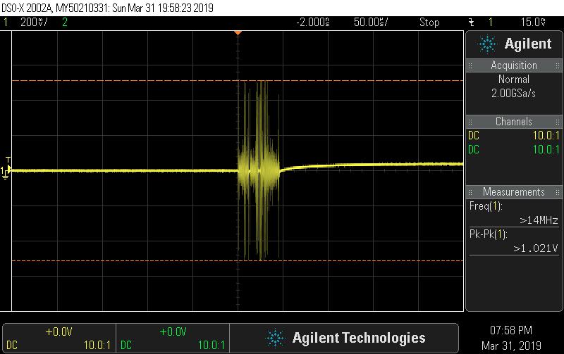
I have performed a very quick and dirty experiment to measure the instantaneous inrush current. I don't have much time to do a proper one. I am not expecting a very high current here, but it will give an idea at least.
1x VE.9bit Phoenix MultiPlus 12/2000/80
1x 12 12Ah SLA battery (a tiny battery).
1x 500A / 50mV shunt (the one that you get with a BMV).
Spindly thin wires (6mm2 aka 10AWG AFAIK).

The MultiPlus switch os in the OFF position, I am simply slamming the connector onto the battery terminal with the oscilloscope connected across the shunt.

So with 200mV per division there is 500mV zero to peak. With 50mV / 500A there is 5000A of inrush current being measured which goes on for roughly 50uS before the oscillations stop.

5000A is quite reasonable I suppose for a little setup, but with a proper setup, a good size battery bank, proper cables and a faster switching time I'm sure much higher inrush currents can be achieved.


scope-22.jpg (55.0 KiB)
1 comment
2 |3000

Up to 8 attachments (including images) can be used with a maximum of 190.8 MiB each and 286.6 MiB total.

kai avatar image kai ♦ commented ·

Love these quick and dirty experiments :P

Unless the OP has a really long wiring run - unlikely as it violates the multiplus installation instructions - its suggestive that action (whether it be precharge or something else) is needed before contactor closes to avoid contact weld.

0 Likes 0 ·
ohiobrits1 avatar image
ohiobrits1 answered ·

Thanks everyone for the input, greatly appreciated and very helpful. I have some good input now to help me investigate my setup further and develop a workable solution.

Thanks again.

2 |3000

Up to 8 attachments (including images) can be used with a maximum of 190.8 MiB each and 286.6 MiB total.