I'm still new to victron but today I noticed my DC load go negative. What does that mean?
Currently my camper is sitting with no shore power and only the 12v refrigerator running.
This site is now in read-only archive mode. Please move all discussion, and create a new account at the new Victron Community site.
I'm still new to victron but today I noticed my DC load go negative. What does that mean?
Currently my camper is sitting with no shore power and only the 12v refrigerator running.

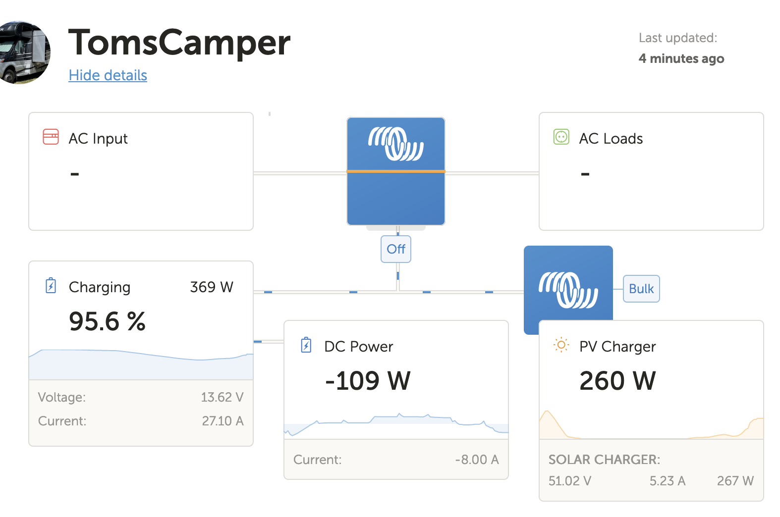
A negative DC load is indicating ingoing charge, most probably from a Victron source or 3rd party charger, which is not connected to your GX device. As you can see, the battery is being charged with 369W. 260W coming from your MPPT and another 109W from another charge source.
Agree that is what it looks like. However the RV is not connected to shore power. It’s isolated from the chassis battery. There is no other charging source.
Could I have something wired incorrectly?
>> Could I have something wired incorrectly? <<
Maybe you wanna share a wiring diagram or images of your installation. And how exactly did you wire the BMV/SmartShunt?
Do you have any sort of alternator charge to the batteries? Like a DC-DC charger or even a parallel connection to starter battery?
I see this output whenever my engine starts and my Orion charger kicks on. It’s a bit of a lame number because it’s showing my alternator output minus any DC house side loads pulling from it, basically just what current is left over going into my batteries. But it’s around that number under load usually, so that would be my vote.
*** Just noticing you said no starter connection… could the shunt be wired backwards? If you have an ammeter you could verify that current is in fact going into your batteries…
I found out today that when you have a solar controller with panels, the li bim 225 will connect your house batteries to the chassis battery, if the chassis battery is below 12.7v, so that may be complicating things.
To troubleshoot, I disconnected solar and here is an example of my 712 readings, with and without the lights on. Does this look correct to you?
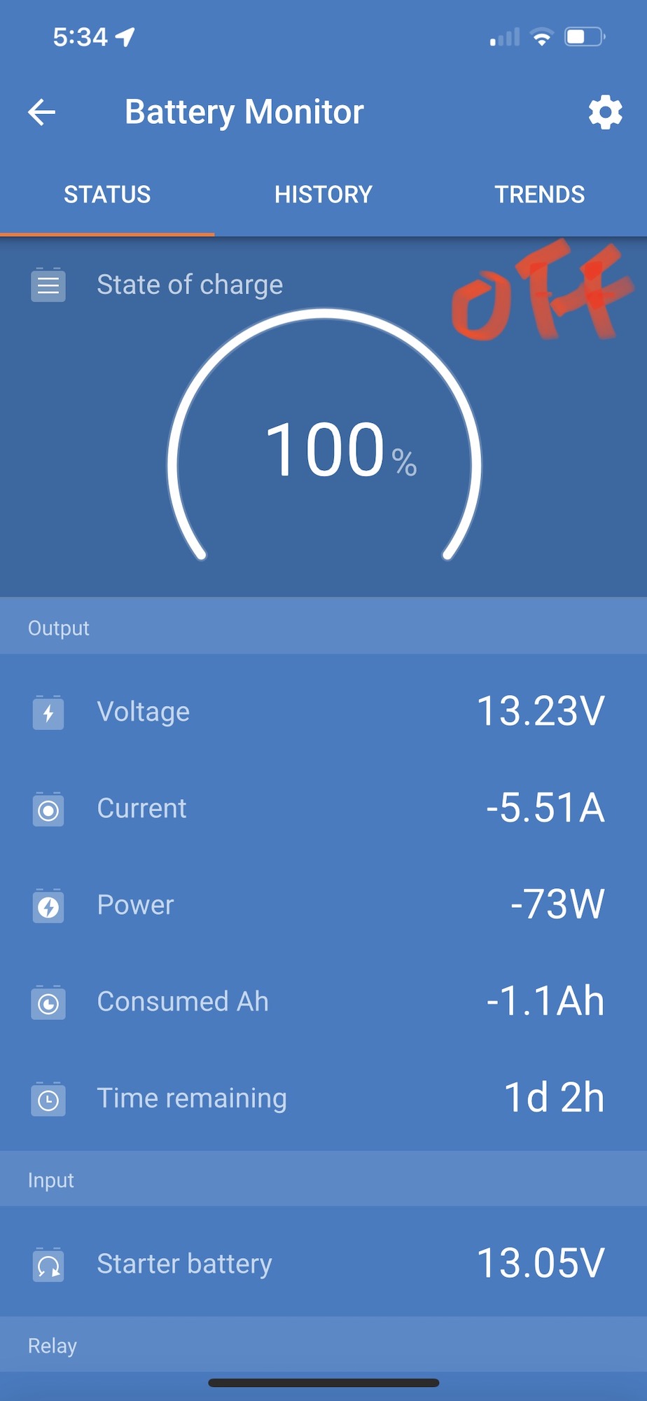
Lights off:
Does this mean with the lights off, the battery is draining at -5.5 amps (my 12 v refrigerator)
Lights on:
And this means with lights on, I'm using 8.88 amps.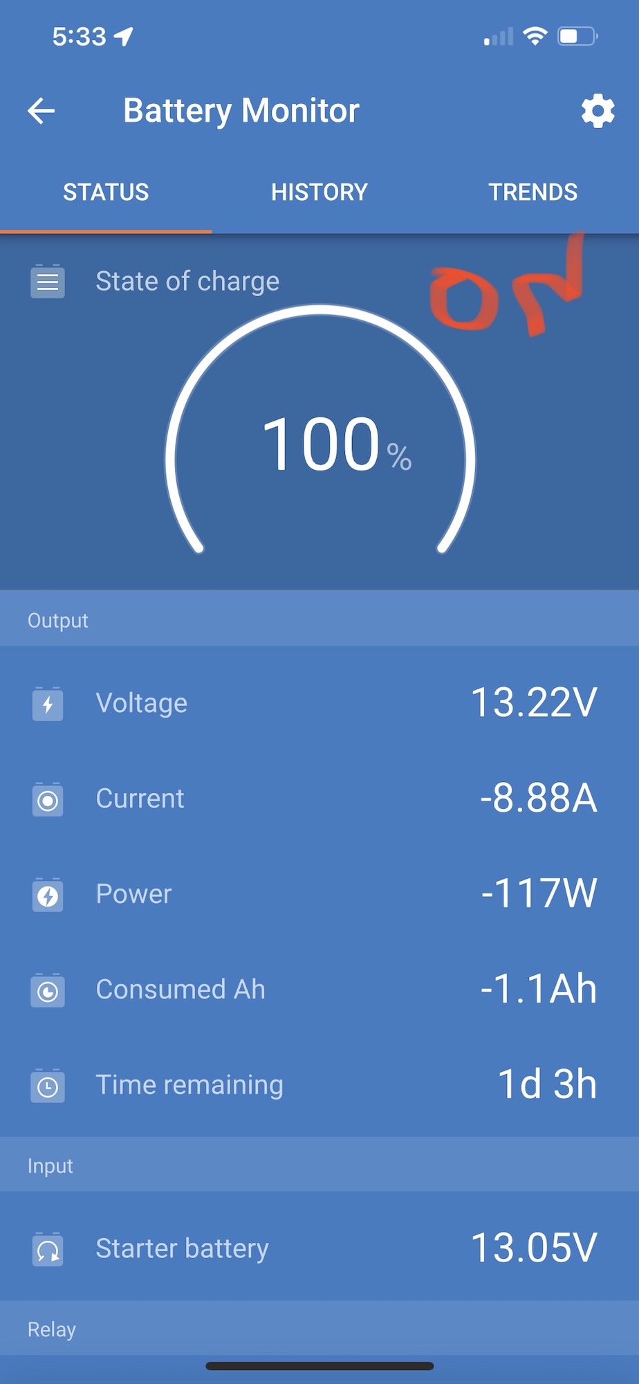
So a negative number here, means current is flowing OUT of the battery. Correct?
This indicates that your fridge is drawing 5.51a and your lights are drawing an additional 3.37a.
Suggest you consider a dc:dc charger in that leg to ensure one way current flow and correct charging of the chassis battery.
Hi kev and thanks for your input. The precision circuits LiBim 225 battery isolator, only connects the batteries together when the chassis battery is low (so solar will charge your chassis battery), or when the engine is running and the house batteries are low (so your alternator can charge your house batteries). It's a very cool device.
I thought it could be causing the problem, but I have verified that the libim is not connecting the batteries together and this problem is unrelated to the libim.
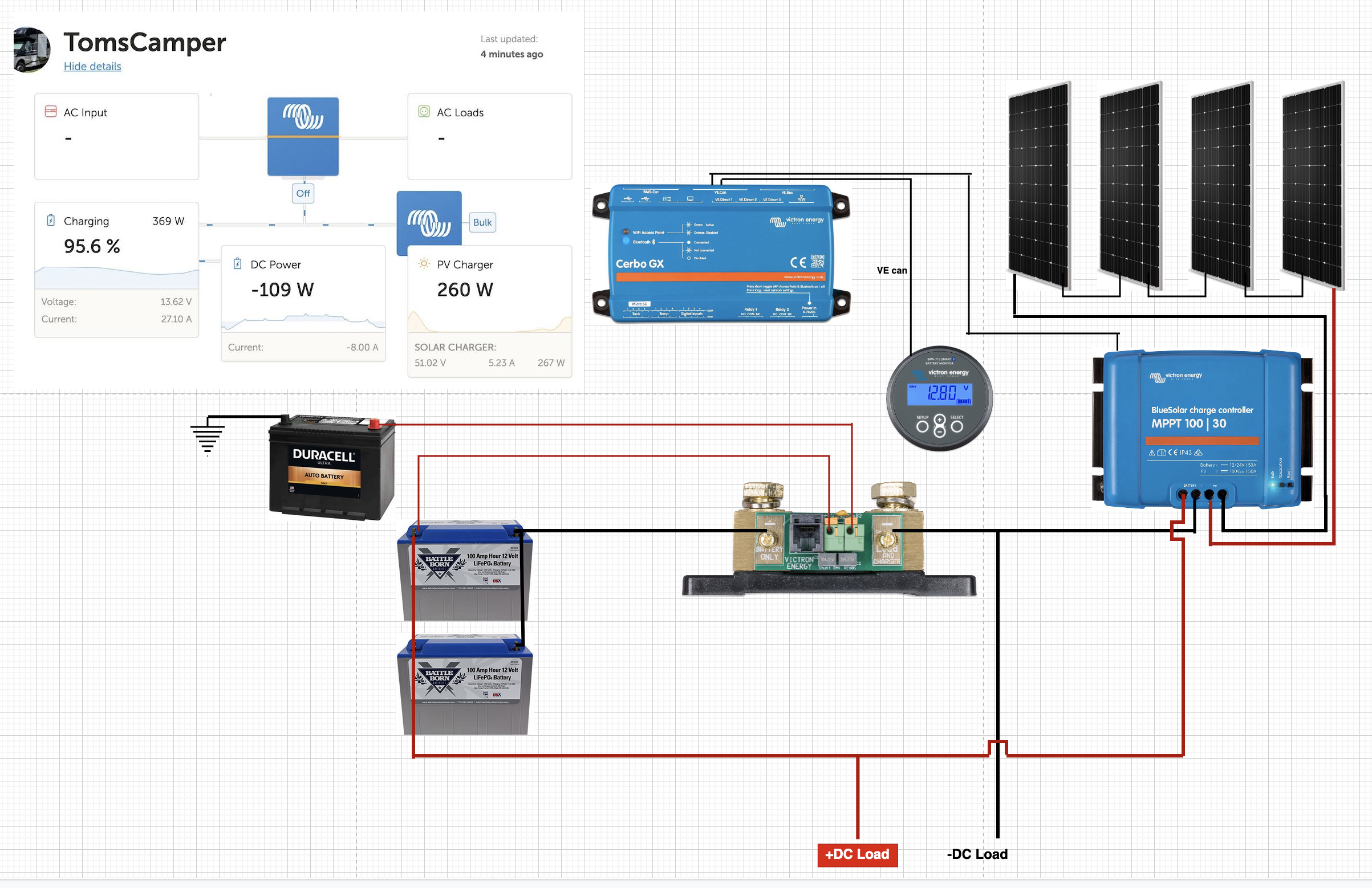
Here is a wiring diagram I made up using app.diagrams.net. I hope this gives you enough information to help me troubleshoot.
Again, this is with NO shore power, no generator, and no other chargers connected. DC load is 12v lights and 12v refrigerator.
1. Why is DC power negative? It's not possible for my lights to put power into the battery. Even if it reads that way, then charging watts should be 151w.
2. If I wire the PV Charger directly to negative battery, that would fix the problem, but then I won't be able to see charging watts, correct?
3. How can it be possible the charging Watts are greater than the PV Charger Watts?
When the PV Charger watts falls below the DC power watts (consumption), all the numbers are correct:
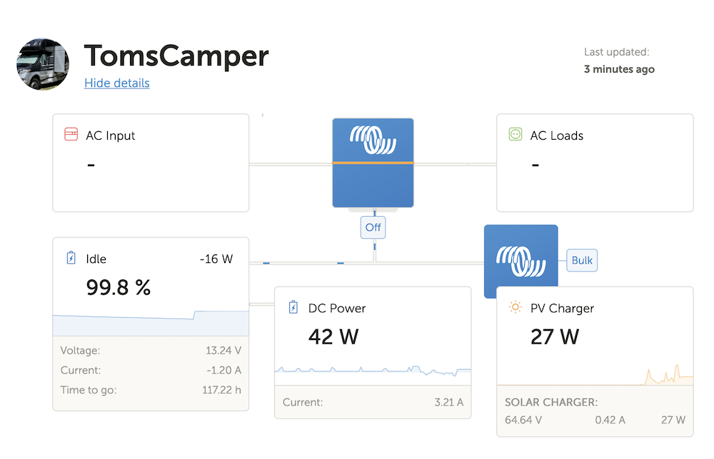
Is the load side of the shunt grounded to frame?
Per the installation instructions for starter battery monitoring, starter battery negative must be connected to the load side of the shunt. Makes the most sense to do it via the ground.
EDIT: Just noticed that you didn't include the BIM. Have you disconnected the li bim 225 from the system to insure that it's not contributing to the issue?
Looks like you're going to have to trace this with a current clamp meter. Starting point would be to measure strength and direction of the current in the three main positive leads. Mppt to junction junction to battery, junction to dc loads. Also as a sanity check, the positive lead between BIM and house bank. Also current into/out of the starter battery. There is only one other source of power, that's the starter battery.
Snoobler, thanks for the tip. I have verified with an OHM meter that both the chassis battery negative and load side of shunt are grounded to chassis. Battery side of shunt also shows grounded to chassis. That is normal, correct?
The Li bim is still in place but I've verified it doesn't have the batteries connected when the problem happens.
Kev, thank you. I've been wanting to get a clamp meter. Obviously I need one that measures DC current, is there anything else I should look for when picking a clamp meter?
Guess it depends on what features you want. Mine has AC/DC volts and current, ohms, diode test continuity, auto scaling, etc. Hold feature I use a lot for those places where you can get the meter in, but can't see the scale. Some are rather bulky, with a wide clamp, great for big cables but often too big to get in where you need it.
Couple of things to watch. Most will only measure the current in a single wire, so if you have a two or three core wire carrying current, you have to find a point where you have a single conductor. The ones that work on two wires are expensive. Mine needs zeroing on DC current. It also defaults to AC, so every time I turn on or change to an AC/DC reading I have to select DC. The other annoyance is that the leads are stiff. So they turn/move the meter. But a set of silicon leads is cheap and much better.
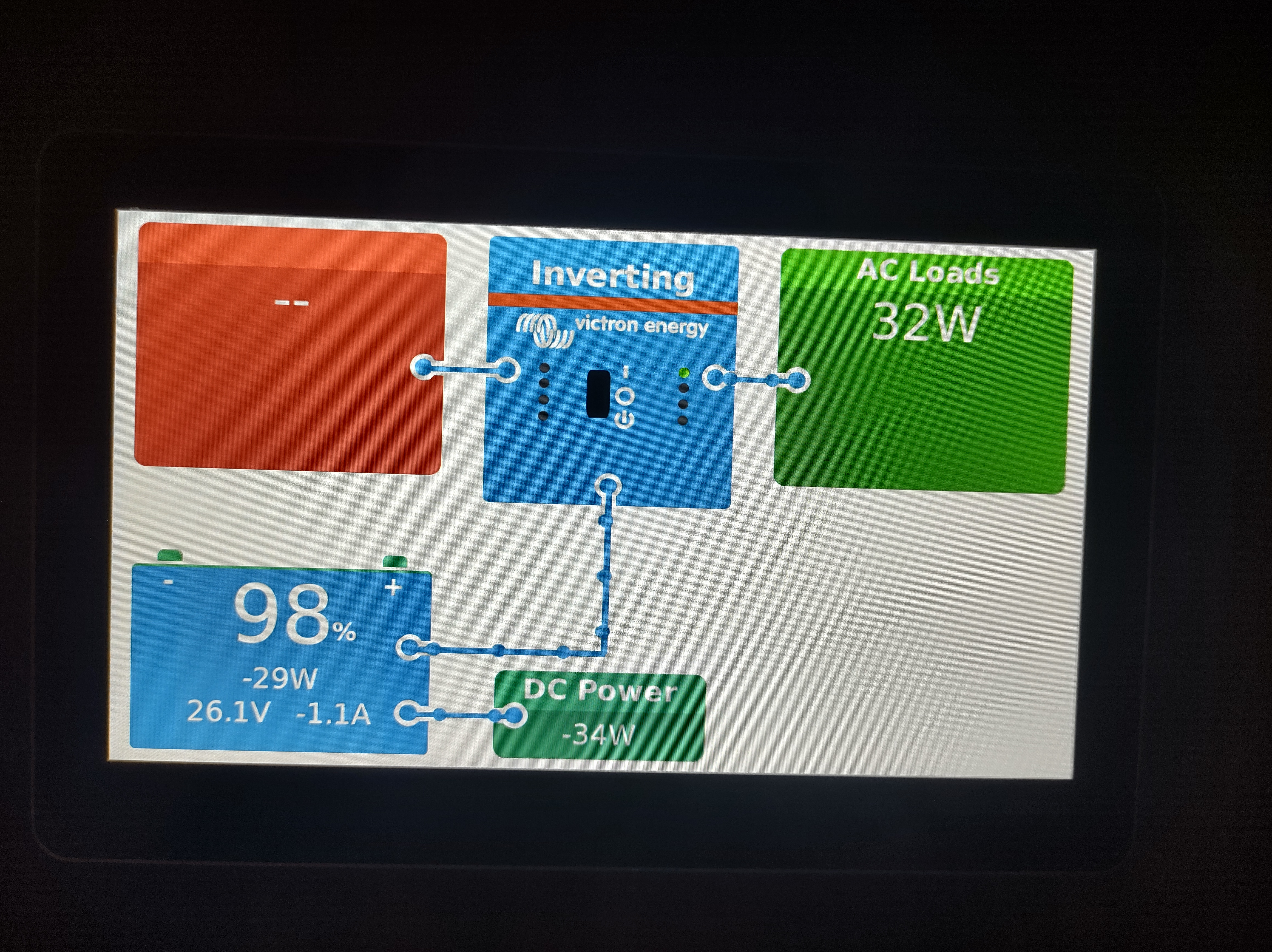
Same problem here (see attached pic) - but I do not have a single charger in the system right now. So there is definitely no DC charging happening at the time of the screenshot.
The whole system is therefore pretty linear at the moment:
(Non-smart) Battery 8s LFP -> JK BMS -> Smart Shunt -> Multiplus | Cerbo.
The MP2-3000 has no grid AC supply plugged in. The smart shunt is configured to "Battery monitor" mode. The "Has DC system" option of the Cerbo is set to "enabled". The AC side is loaded with a small load (microwave oven), which might be not a linear load, especially in standby mode. I guess the 32W measured are apparent power and not active power. Did not cross-check yet, but 32W sounds way to much. The total DC power might be correct considering the MP2 idle consumption and the Cerbo plus 7" display.
I had this happen when I set up my system in reverse w/ the batteries on the right side of the shunt. Reversing the small 5 wires as described elsewhere worked great for me.
https://community.victronenergy.com/questions/82159/lynx-shunt-vecan-installation-and-wiring.ht
I also see negative numbers from the DC power that looks like it is charging the battery from some DC source even though I don't have a DC charging source on.
Additionally, my MPPT often reports up to -15W when the sun isn't shining (although it's 0 when super dark, but I get the negative numbers around twilight).
Additional resources still need to be added for this topic
32 People are following this question.