question

tommas avatar image
tommas asked

ESS drains battery after 100% SOC and 1Hr absorption is reached

When charging the battery to 100% with multiplus and mppt it finally reaches absorption point. After 1Hr of absorption it stops charging and starts to discharge the battery into the grid.

I tried different things to stop it from happening,

- update newest firware tot the multi,

- update mppt,

- even downgrade the venusOS to 2.22 instead of the 2.23 i was running.

- pull out the mppt cable(maybe it sends faulty values, but it wasnt)

- resetted all devices..


it keeps discharging battery to grid. I have no clue what to do next...for now i disconnect the mains to stop it. Anyone who has an idea?

thanks in advance, Tommas


Setup:

multiplus

mppt75/50

RaspberryPI with venus image (ESS-optimized w/ battery life, feed-in allowed, 35% min. SOC)

bmv700

LiFePo4 25.6V 7kWh battery with 2-wire BMS


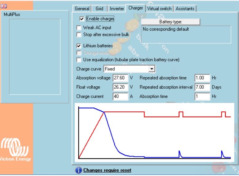
in the multi charger tab set the next values: (27.60V / 8cell = 3,45V/cell)
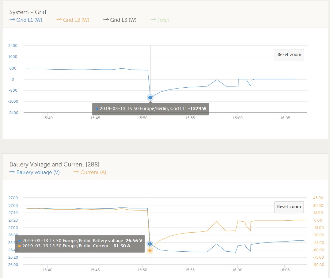
the curve is a little strange because of disconnecting the mains to stop it.

ESSRaspberry Pi
chargertab.jpg (95.1 KiB)
grid-batt-2.jpg (126.8 KiB)
2 |3000

Up to 8 attachments (including images) can be used with a maximum of 190.8 MiB each and 286.6 MiB total.

3 Answers
wkirby avatar image
wkirby answered ·

It discharges in an effort to reach the Float Voltage. Once the battery has reached the Float Voltage it should gradually stop discharging then just excess PV power will go into the grid.

2 comments
2 |3000

Up to 8 attachments (including images) can be used with a maximum of 190.8 MiB each and 286.6 MiB total.

tommas avatar image tommas commented ·

Thanks, i will look at it! and add feedback if it works that way.

0 Likes 0 ·
tommas avatar image tommas tommas commented ·

It works that way! Great. Ive set the float voltage to low(because i lowered the absorption voltage i also lowered the float voltage. But that wasnt the way to go). My fault, but youre right and all runs well now.

0 Likes 0 ·
Rob Duthie avatar image
Rob Duthie answered ·

Hi

I have the same situation with a Mulitplus2 unit with lithium battery setup using Nissan leaf packs 7s2p

All firmware has has being updated to the latest to date 5/5/2019

Raspberry Pi used version 2.30.45 and older version same effect.

Except mine keeps dumping down to the SOC limit set points at 50%

And dumps the whole 3kw rated power of the inverter into the grid. plus any solar generation combined so it can output over 5kw back into the grid. Not a good idea.

I have noticed this happens when the sun stop shining and there is not much load as it flicks over it cant flick back again and gets stuck in discharging. i have turned of the power assist feature.

This is a random problem, i am testing and changing parameters to see what the effect are.


3 comments
2 |3000

Up to 8 attachments (including images) can be used with a maximum of 190.8 MiB each and 286.6 MiB total.

sean avatar image sean commented ·

How is your ESS metering grid consumption ? CT or perhaps the CG smart meter ?

0 Likes 0 ·
Show more comments
Rob Duthie avatar image
Rob Duthie answered ·

-what components are in the system? Mulitplus2 (where is PV connected) at the output 1

-what firmware versions? 2625-459

-what BMS are you using? none not required stand a loan system Nissan leaf

-what inverter settings? as below

-What is set as battery monitor? as below

-What ESS settings? as below

TAB: General
System frequency 50Hz
Shore current 32.0 A
Overruled by remote checked
Dynamic current limiter unchecked
State of charge when Bulk finished 95.0 %
Battery capacity 64 Ah
Charge efficiency 0.95
TAB: Grid
Country / grid code standard New Zealand: AS/NZS 4777.2:2015
LOM detection AC input 1 Type B (grid code compliant)
TAB: AS/NZS 4777 grid code settings
rise-in-voltage protection U> 258.0 V
Power ramp time 60 seconds
Enable DRM0 functionality unchecked
Fstop for sustained high frequency operation 52.00 Hz
Volt-Watt curve voltage V1 207.0 V
Volt-Watt curve level at V1 0 %
Volt-Watt curve voltage V2 220.0 V
Volt-Watt curve level at V2 100 %
Volt-Watt curve voltage V3 244.0 V
Volt-Watt curve level at V3 100 %
Volt-Watt curve voltage V4 255.0 V
Volt-Watt curve level at V4 100 %
TAB: Inverter
PowerAssist checked
Assist current boost factor 2.0
Inverter output voltage 230 V
Inverter DC shut-down voltage 42.00 V
Inverter DC restart voltage 46.00 V
Low DC alarm level 45.00 V
Do not restart after short-circuit (VDE 4105-2 safety) unchecked
enable AES unchecked
TAB: Charger
Enable charger checked
Weak AC input unchecked
Stop after excessive bulk unchecked
Lithium batteries unchecked
Storage mode unchecked
Use equalization (tubular plate traction battery curve) unchecked
Charge curve Fixed
Absorption voltage 56.80 V
Float voltage 54.00 V
Charge current 35 A
Repeated absorption time 1.00 Hr
Repeated absorption interval 7.00 Days
Absorption time 1 Hr
TAB: Virtual switch
TAB: Usage
Virtual switch usage Do not use VS
TAB: Assistants
TAB: Assistant Configuration
ESS (Energy Storage System) (size:1621)
*) System uses LiFePo4 with other type BMS
(This can be either a BMS connected via CAN bus or a BMS system in which the
batteries are protected from high/low cell voltages by external equipment.)
*) The battery capacity of the system is 64 Ah.
*) Sustain voltage 50.00 V.
*) Cut off voltage for a discharge current of:
0.005 C= 52.00 V
0.25 C= 50.00 V
0.7 C= 49.20 V
2 C= 48.00 V
*) Inverting is allowed again when voltage rises 1.20 V above cut-off(0).
*) The solar converter will start reducing its output power at 50.20 Hz.
Output power will be reduced to minimum when the frequency is 52.70 Hz.
The converter will disconnect when the frequency is higher than 53.00 Hz.
*) Total installed PV inverter power is 2000 Watts.
Total installed PV panel power is 2000 Watts.
*) Relevant VEConfigure settings:
- Battery capacity 64 Ah.
- PowerAssist checked
- Lithium batteries unchecked
- Dynamic current limiter unchecked
- Storage mode unchecked


Total size of all assistants including the required
(hidden) system assistants is: 1694

7 comments
2 |3000

Up to 8 attachments (including images) can be used with a maximum of 190.8 MiB each and 286.6 MiB total.

boekel avatar image boekel ♦ commented ·

Ok, some things I noticed:

-what BMS are you using? none not required stand a loan system Nissan leaf

So it has an internal bms that cuts off the battery from the system?


Absorption voltage 56.80 V
Float voltage 54.00 V

That's your problem, just as the original topic starter:

-after reaching Absorbtion (4,05V per cell) it will discharge to reach Float voltage (3,85V per cell), this is about 50% SOC


*) Cut off voltage for a discharge current of:
0.005 C= 52.00 V
0.25 C= 50.00 V
0.7 C= 49.20 V
2 C= 48.00 V

for lithium: use the same value for all settings, normal cutoff voltage

The battery capacity of the system is 64 Ah

is this the capacity from 56,8 to 42V?

BTW, 42V is very low, the cells are pretty much empty at 46V so I'd use a voltage somewhere around that, or higher (to leave some capacity below inverter shutdown, preventing draining the batteries)

0 Likes 0 ·
Rob Duthie avatar image Rob Duthie boekel ♦ commented ·

Hi

Thanks for that, i used a wrong calculations based on the 7 cells which are 2 cells in series and 2 in parallel. 8 volt cell modules

Just trying to find the correct float voltage on these Nissan leaf cells.

Some say just to set it just below or the same as the Absorption voltage?

I think this is were what my problem is.

What is the percentage from absorption to float in % ?


Estimated cells graph voltages for the Leaf cells

Charge Termination: 4.10V
Discharge Low Battery Warning: 3.77V
Discharge Very Low Battery Warning: 3.625V
Discharge Turtle Mode (Protect): 3.22V
Discharge Dead (Shutdown): 3.20V

0 Likes 0 ·
boekel avatar image boekel ♦ Rob Duthie commented ·

It's lithium ion, you don't use 'float charge' so you set the float voltage the same as absorbtion or a little below. (if it was LiFe(Y)PO4 you would use float at a lower voltage)
So what is the configuration? 7s or 8s?

You haven't answered the questions btw:

-what kind of bms system is in the battery?
-how does the bms communicate with the Victron system? or does it disconnect? if so: at what voltages?

0 Likes 0 ·
Rob Duthie avatar image Rob Duthie boekel ♦ commented ·

Hi

Yes i have reset the cell float and absorption as per Nissan leaf cell guide.

57.4 =4.1 per cell

57 =4.07 per cell

The cell at float now is 98% charged

After these changes it has worked perfectly, not discharging so low now.

Resest my ESS back to lithium mode etc.

I have down graded it slightly to save ware on the cells, as recommend.

7 in series is the correct arrangement for these cells.

No BMS at this stage. as other don't use it, and had no problems, as long as the cells are balanced at first when setting up.

I will be adding one later on, which i plan to use a EMUS BMS Mini from Lithuania, They plan to update the software so it can talk to the Victron units via Canbus etc.

https://emusbms.com/product/bms-mini?all_versions=mini-firmware#mini-firmware


Pass it on, might be helpful for others wanting to use Nissan leaf cells modules.


0 Likes 0 ·
boekel avatar image boekel ♦ Rob Duthie commented ·

REC has a BMS that has been working well for a while, might be an option.

I really have to emphasize to not run a lithium battery without BMS

http://www.rec-bms.com/BMS16S.html

0 Likes 0 ·
Rob Duthie avatar image Rob Duthie boekel ♦ commented ·

Hi Yes i know of them, they are so expensive compared to the emusbms, plus you have to buy all the bluetooth comms and sensors are all extra cost not included, unlike emusbms units. which include all

and much cheaper and they are releasing a Victron Canbus software for canbus control.

0 Likes 0 ·
Phil Gavin avatar image Phil Gavin Rob Duthie commented ·

Rob,

Did you get the EMUSBMS commissioned yet?


0 Likes 0 ·