question

bezda avatar image
bezda asked

Wakespeed and Lynx BMS wiring

Hi, looking at recommended wiring of WS500 to Lynx Smart BMS, I don't quite understand why is AUX connected to ATC and that is then connected to relay.


- What is the purpose of going via ATC?

- Won't that just effectively disable ATC signal for any other devices, since there will always be signal from AUX?

- The WS500 ATC + (Charge Enable) is connected to the relays NO that closes when an alarm is active, shouldn't it be connected to NC?
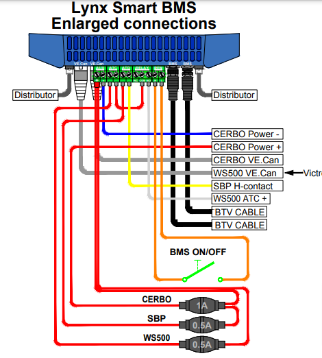

download.png


https://www.victronenergy.com/upload/documents/MultiPlus-3KW-230VAC-12VDC-600Ah-Li-Lynx-Smart-BMS-&-distributors-Cerbo-GX-touch-generator-MPPT-Extra-Alternator-&-WS500.pdf

BMS
download.png (93.4 KiB)
2 |3000

Up to 8 attachments (including images) can be used with a maximum of 190.8 MiB each and 286.6 MiB total.

3 Answers
bomax182 avatar image
bomax182 answered ·

Working through the same issue/questions now, 3 years later. Thought I would post my findings to help others, and perhaps have my understanding confirmed by the actual experts here.

Regarding "What is the purpose of going via ATC? Won't that just effectively disable ATC signal for any other devices, since there will always be signal from AUX?" Pins 3 and 5 provide the power to the ATC/ATD relays respectively, which comes out on pins 4 and 6. Since ATC/ATD are simple relays, they merely close (connect the pins) or open (disconnect then).

And regarding "The WS500 ATC + (Charge Enable) is connected to the relays NO that closes when an alarm is active, shouldn't it be connected to NC?"

Go in through the Cerbo menu and change the programmable relay to Alternator ATC mode. This changes the behavior of that relay to no longer work based on alarms, and instead energize/close the relay when charging is permitted and de-energize/open when the alternator should stop. It will do this at least 2 seconds before the main contactor is opened for safety.

My understanding is COM is the "input" and NO and NC are outputs that are inverse of each other (one is "on" when the other is "off").

2 |3000

Up to 8 attachments (including images) can be used with a maximum of 190.8 MiB each and 286.6 MiB total.

mattyroo avatar image
mattyroo answered ·

In reality with the latest WS firmware of 2.5.2 the ATC should never come into play, as the latest FW allows DVCC control of the WS.

2 |3000

Up to 8 attachments (including images) can be used with a maximum of 190.8 MiB each and 286.6 MiB total.

bomax182 avatar image
bomax182 answered ·

True, but in my case I want to add an inline switch so that I can manually disable charging via alternator when it’s not needed.

1 comment
2 |3000

Up to 8 attachments (including images) can be used with a maximum of 190.8 MiB each and 286.6 MiB total.

mattyroo avatar image mattyroo commented ·
You will need to be careful doing this, if you open that switch whilst producing current, you'll blow the diode pack in the alternator. Best to fit a surge protector inline.

This is where the Zeus' have it allover the WS500's, as you can do thsi safely with bluetooth.

0 Likes 0 ·

Related Resources

Additional resources still need to be added for this topic