question

Rob Beckers avatar image
Rob Beckers asked

MultiPlus 3000 exceeding absorb Voltage

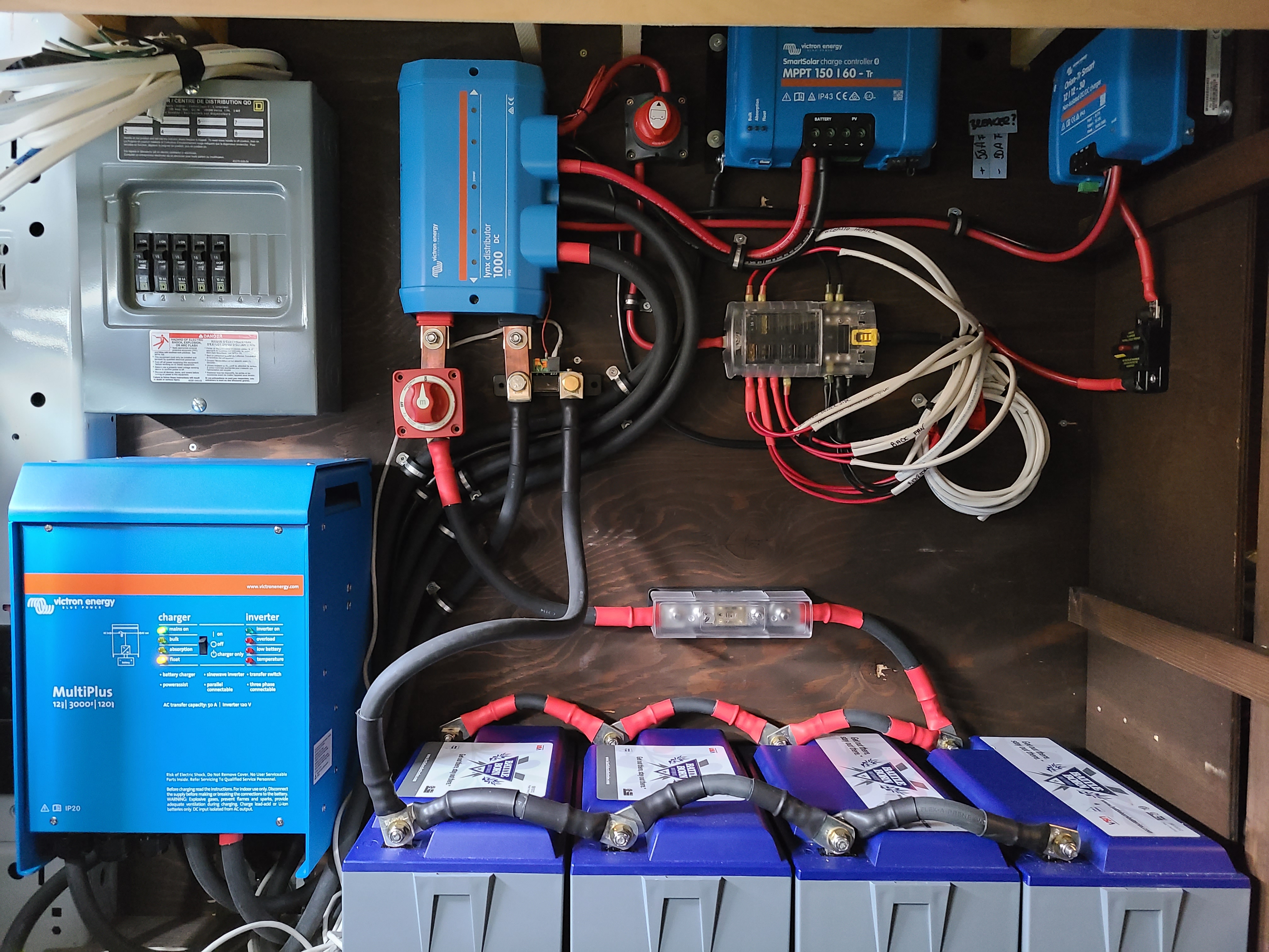
One of our customers has an RV with a MultiPlus 12/3000 installed, and 4x Battle Born 100Ah 12V lithium-ion batteries in parallel. The only charging source at this time is shore-power.

She reports strange behavior when the MultiPlus goes into absorb; the lights flicker, fans beep due to under-Voltage and such. I had her measure the Voltage while charging and it was in the high-15V range, touching on 16V at times!

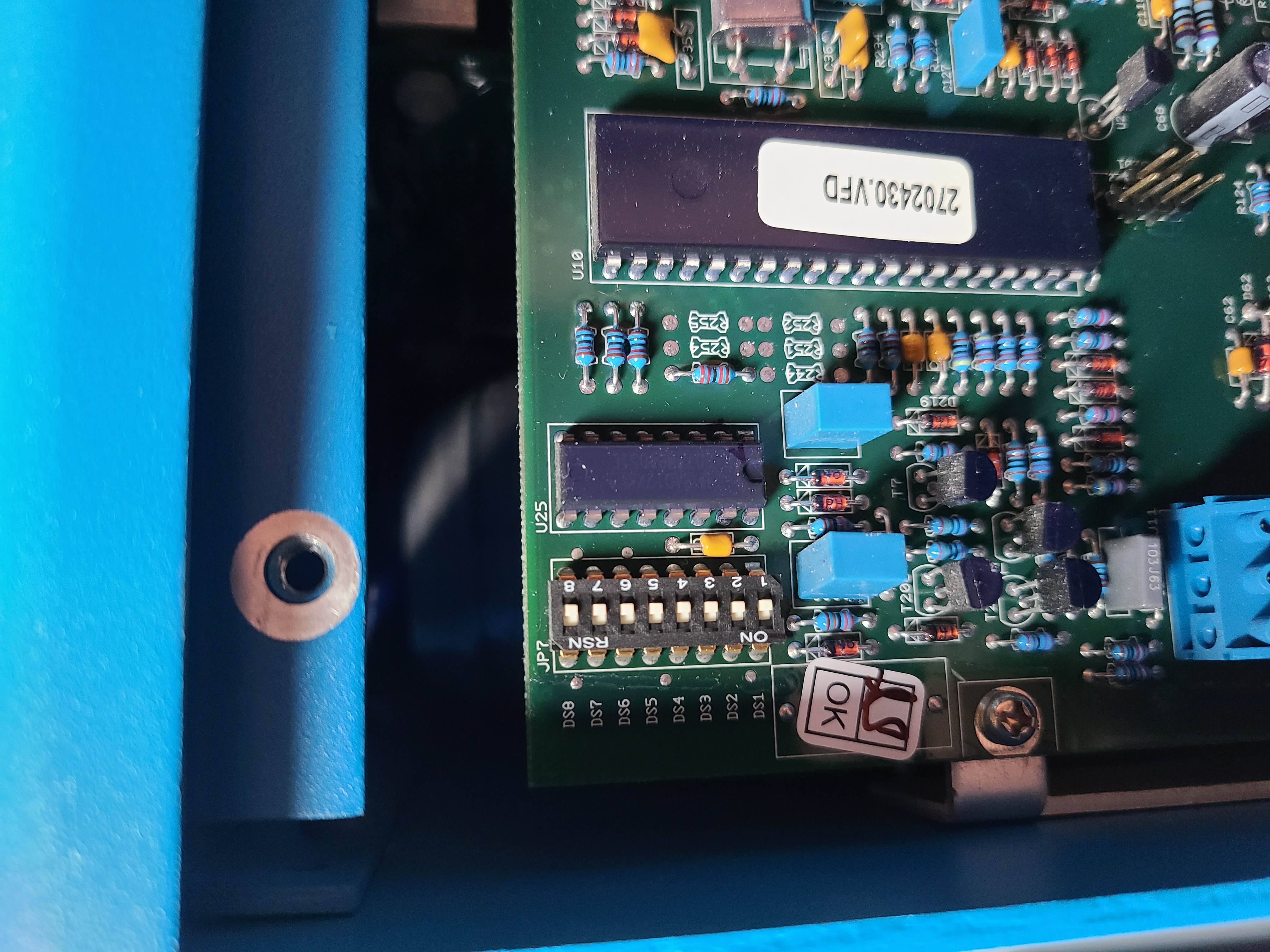
The DIP-switches on the MultiPlus are all set to "off" which would mean the absorb Voltage is 14.1 Volt, and there is no temp-sensor attached (so not temperature compensation, as it should be for lithium-ion batteries). Very likely the BMS in the batteries is switching off due to over-Voltage, and that's causing the effects she's seeing with the appliances.

The question is: What could cause the MultiPlus to exceed its set absorb Voltage of 14.1 Volt??

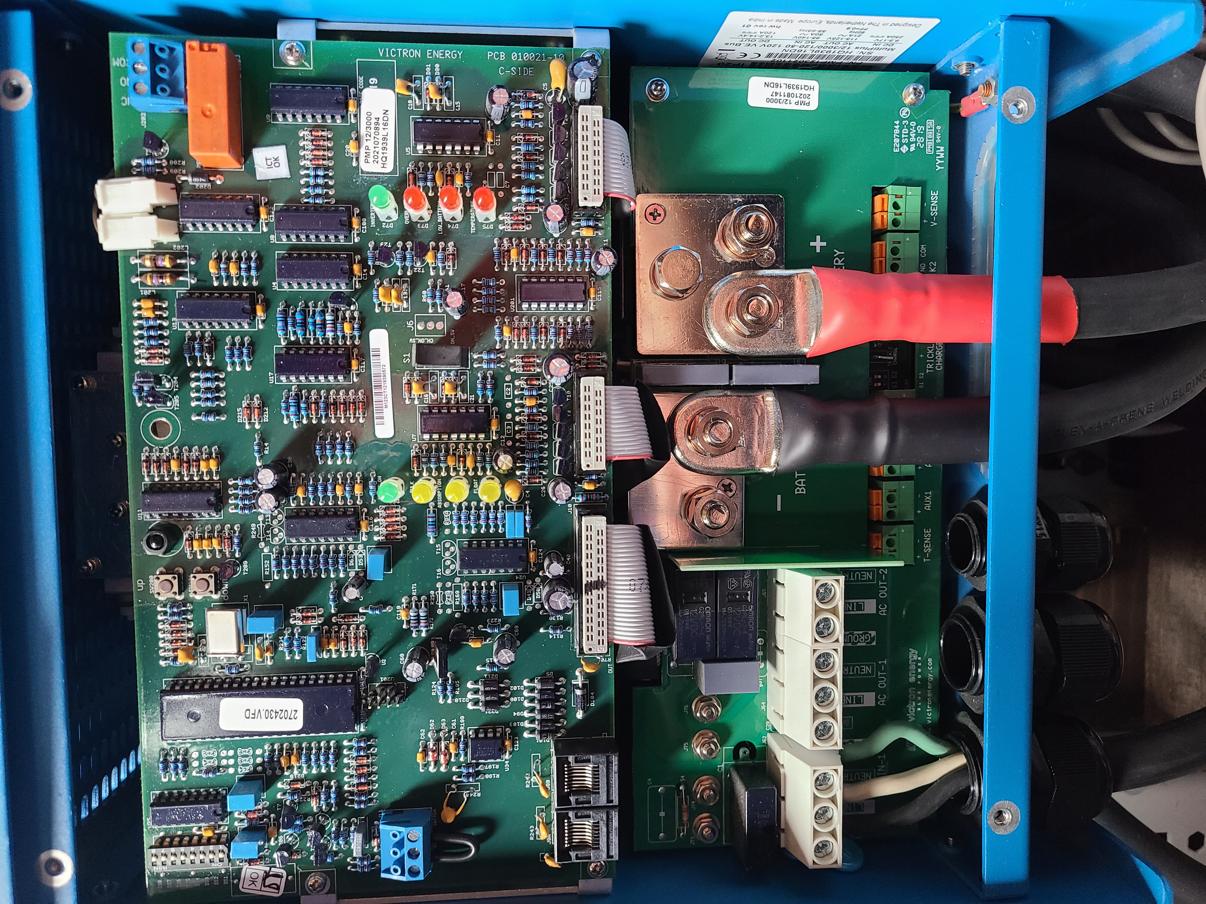
Pictures of the install are attached (and no, there are no solar panels installed yet, despite the SmartSolar in the picture, so that charge controller is doing nothing).


Thank you for your help!

-Rob-

Solacity Inc.
20211117-102152-1.jpg20211124-092550.jpg20211124-092609.jpg


MultiPlus Quattro Inverter Charger
2 |3000

Up to 8 attachments (including images) can be used with a maximum of 190.8 MiB each and 286.6 MiB total.

11 Answers
Alexandra avatar image
Alexandra answered ·

@Rob Beckers

Have you verified with a meter?

If it is exceeding absorption voltage it is very likely the batteries are shutting down to protect themselves.

Also using dip switches is a black art. Their current positions does not indicate how it is programmed in any way.

It is best to have a gx device in the system and an mk3 to usb adaptor used with ve config or victron connect, to make sure things are set right in software and are functioning correctly.

2 |3000

Up to 8 attachments (including images) can be used with a maximum of 190.8 MiB each and 286.6 MiB total.

Rob Beckers avatar image
Rob Beckers answered ·

Thank your for your reply Alexandra!

The absorb/battery Voltage was verified by the customer using a multimeter. Unfortunately they are 4000km away from our shop (clear across the country), and they don't have a MK3-USB. So I cannot personally verify what the internal settings are. The MultiPlus is a brand-new unit just out of the box, so we can be pretty certain nothing was set in memory besides the defaults, which best I understand means it should honour the DIP-switch settings.

-Rob-

2 |3000

Up to 8 attachments (including images) can be used with a maximum of 190.8 MiB each and 286.6 MiB total.

Rob Beckers avatar image
Rob Beckers answered ·

Alexandra, just read through your link about programming by using the DIP-switches; it's a little different from how I thought this was working and very informative! I'll give the customer a call and see if we can talk her through setting some explicit charge settings using those switches, and storing them.

Will report back with the result.

Thanks again!

-Rob-

2 |3000

Up to 8 attachments (including images) can be used with a maximum of 190.8 MiB each and 286.6 MiB total.

Rob Beckers avatar image
Rob Beckers answered ·

The customer and I sent over setting the charge parameters, following the instructions. While I cannot verify what is set, I am confident she did everything correctly, and we should have the unit at 14.1 Volt for bulk/absorb.

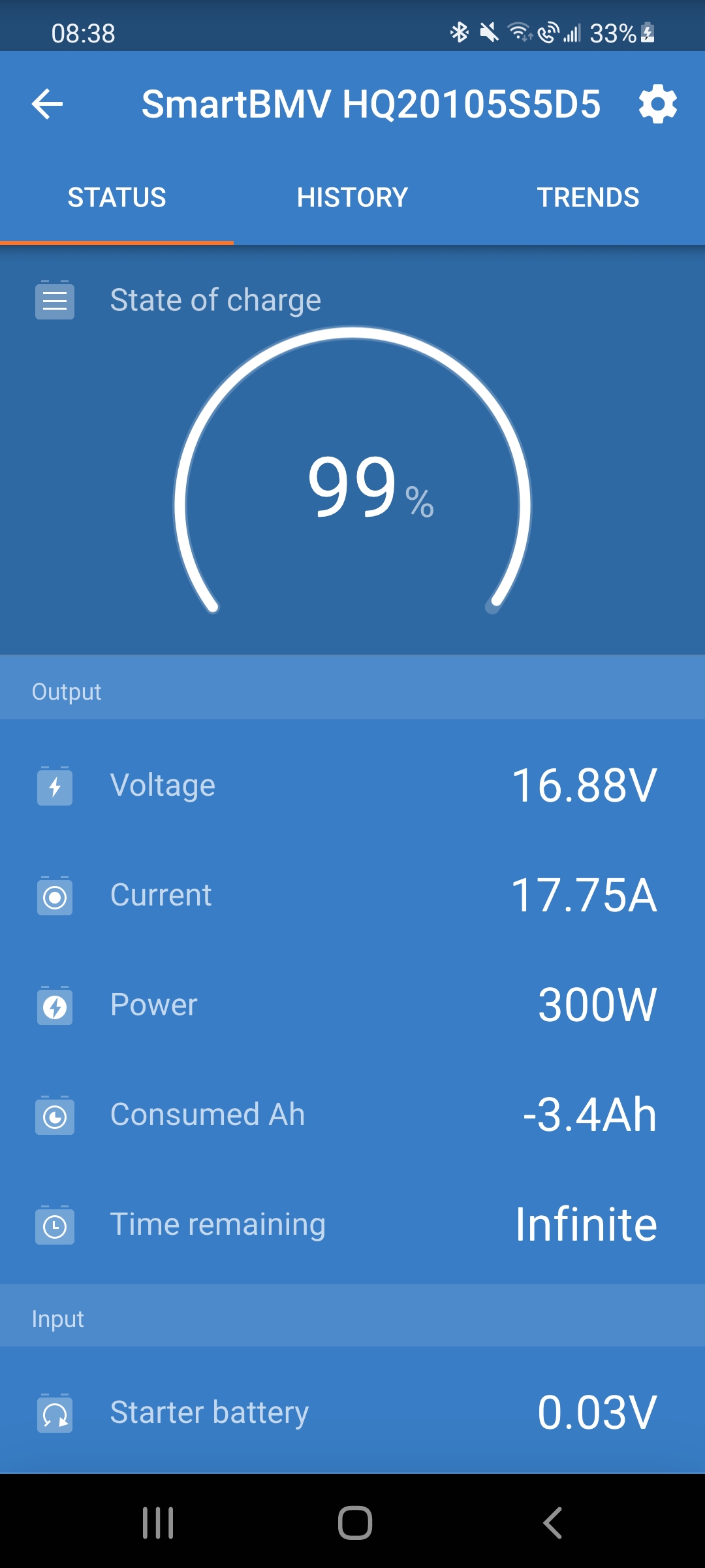
Despite that, charging via the still runs the Voltage up to 16+ Volt (and to a point where I'm pretty sure the BMS switches off the batteries). Screenshot from the BMV-712 attached.

-Rob-

screenshot-20211125-083850-1.jpg


2 comments
2 |3000

Up to 8 attachments (including images) can be used with a maximum of 190.8 MiB each and 286.6 MiB total.

Alexandra avatar image Alexandra ♦ commented ·

@Rob Beckers

it is possible it is set for lead acid and it is trying to equalize. So battery tpe is incorrect possibly

the mppts can be changed.

0 Likes 0 ·
Rob Beckers avatar image Rob Beckers commented ·
Alexandra, not that I know.

What I'm going to suggest is that the customer gets an MK3-USB, and hooks the inverter up to a computer. That way we can actually verify and positively set the Voltages. That will likely also update the firmware to the latest, who knows, maybe that's part of the problem.\

-Rob-

0 Likes 0 ·
kevgermany avatar image
kevgermany answered ·

The multi looks to be in float.

There's a 12:12 Orion in there. Is that wired to charge the house batteries? Did the customer set/check that?

And interestingly the starter battery is shown close to zero volts. Is that not wired in, or incorrectly wired?

2 |3000

Up to 8 attachments (including images) can be used with a maximum of 190.8 MiB each and 286.6 MiB total.

Rob Beckers avatar image
Rob Beckers answered ·

The orion is a DC-to-DC charger for when the engine is running (charge from alternator). The screenshot is when the engine is not running, as were the earlier measurements. Solar is not hooked up, the only charging source is the MultiPlus.

Noticed the zero Volt starter battery as well. I've not asked but assume it's just not hooked up.

-Rob-

2 |3000

Up to 8 attachments (including images) can be used with a maximum of 190.8 MiB each and 286.6 MiB total.

amgrumpy avatar image
amgrumpy answered ·

Hi,the owner didn't run the batteries down to low voltage disconnect by any chance before charging on mains?

Cause this happened to me with lifepo4 in an easy solar unit everything was sweet for months until i decided to test battery capacity.I ran them down until disconnect,im not sure whether it was easy solar or batts that shut off first as im on a learning curve :-) i then plugged into 240v and at absorption the voltage went nuts until bms disconnected.

I took to victron installer/rv mechanic,they just did a firmware update,set parameters again,monitored unit and it came good,so i dont have a specific reason only that a reset/update of unit fixed it.

Cheers.


1 comment
2 |3000

Up to 8 attachments (including images) can be used with a maximum of 190.8 MiB each and 286.6 MiB total.

Rob Beckers avatar image Rob Beckers commented ·
Nope, batteries are switched on (the BMS that is). When not charging a stable Voltage is present. What is IMO happening is that the BMS in all of the batteries is switching off based on over-Voltage, and at that point the MultiPlus spikes at 16+ Volt (the BMS in these batteries kicks out around 15 Volt).

Of course, the real question is why the MultiPlus runs the Voltage up THIS high to get to the point of causing the BMS to disconnect...

-Rob-

0 Likes 0 ·
Paul B avatar image
Paul B answered ·

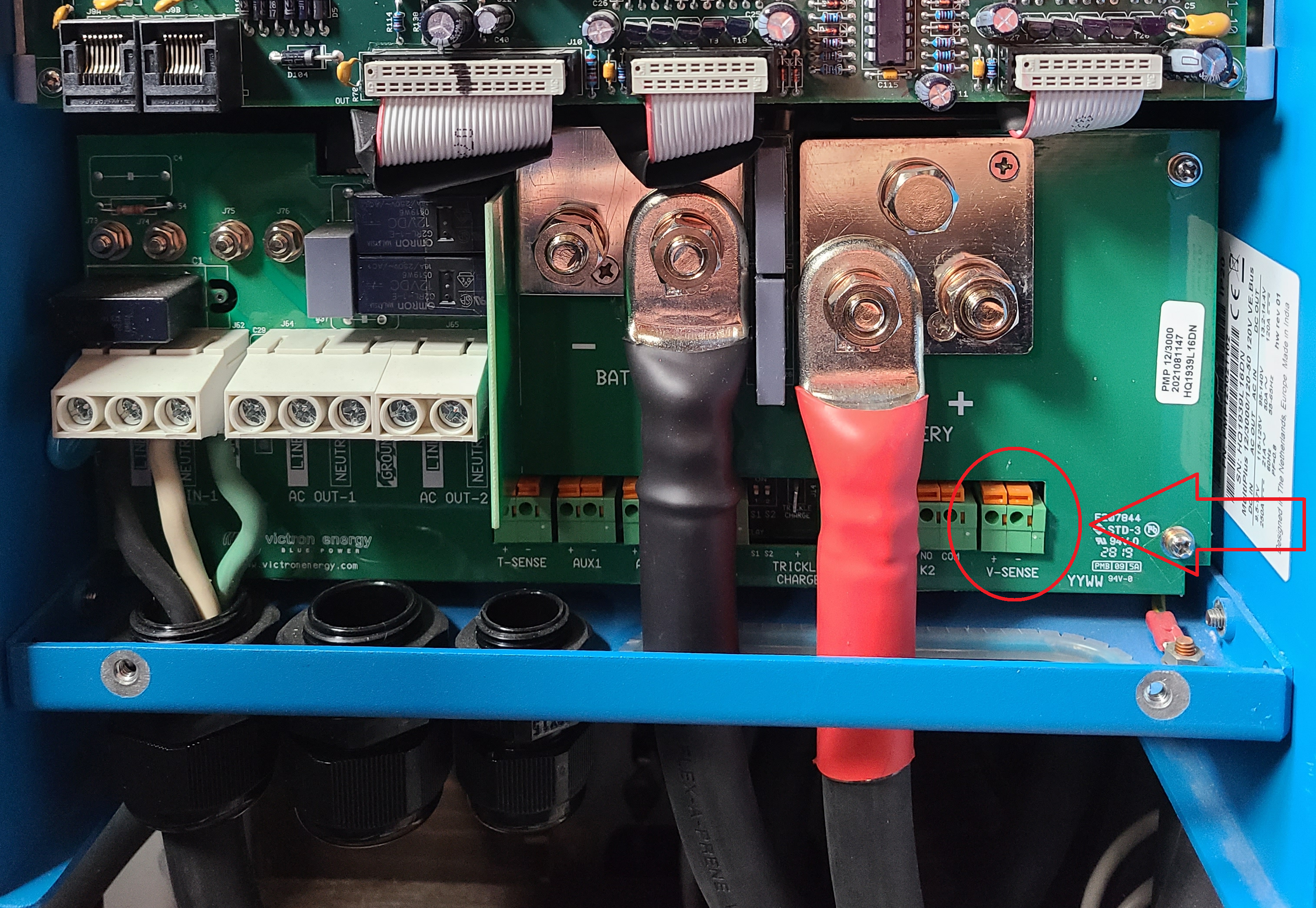
From the picture you dont seem to have a voltage Vsense connected

check the Multiplus Reference voltage connections are on the correct battery bank, and are connected on the NON battery side of any shutoff relay and that its getting the correct voltage reading

2 comments
2 |3000

Up to 8 attachments (including images) can be used with a maximum of 190.8 MiB each and 286.6 MiB total.

Paul B avatar image Paul B commented ·

At a Min connect these to the Multis Pos and Neg terminals - In preference they should be connected to the battery if there is no rely cuttoff anyware.that is

1637999926970.png

0 Likes 0 ·
1637999926970.png (15.2 MiB)
Rob Beckers avatar image Rob Beckers commented ·

Installing battery sense wires won't make any difference in this case. Yes, it gets the inverter a more accurate measurement of the actual battery Voltage, but if all worked as advertised, and even if there's a relevant Voltage drop over the inverter wires, the inverter would/should still not exceed 14.1V at the inverter side of the wiring (and that it's a little lower at the batteries doesn't matter, once the current tapers to zero during absorb the Voltages will be equal). This ain't the problem...

-Rob-

0 Likes 0 ·
Rob Beckers avatar image
Rob Beckers answered ·

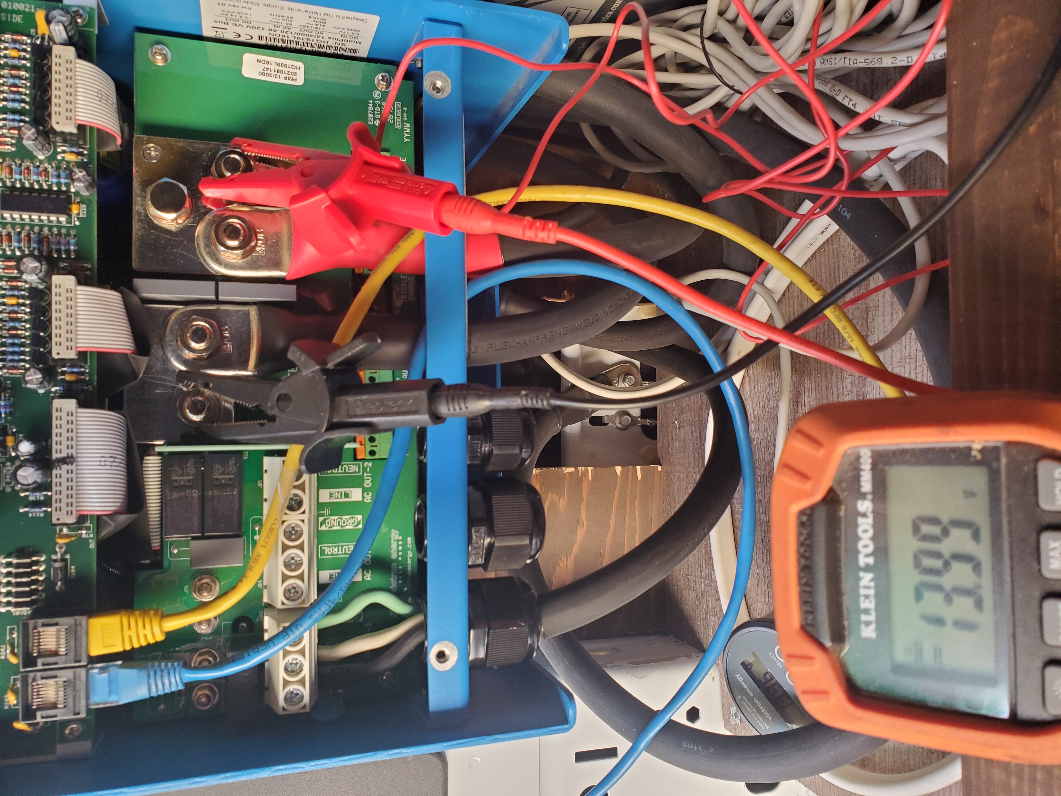
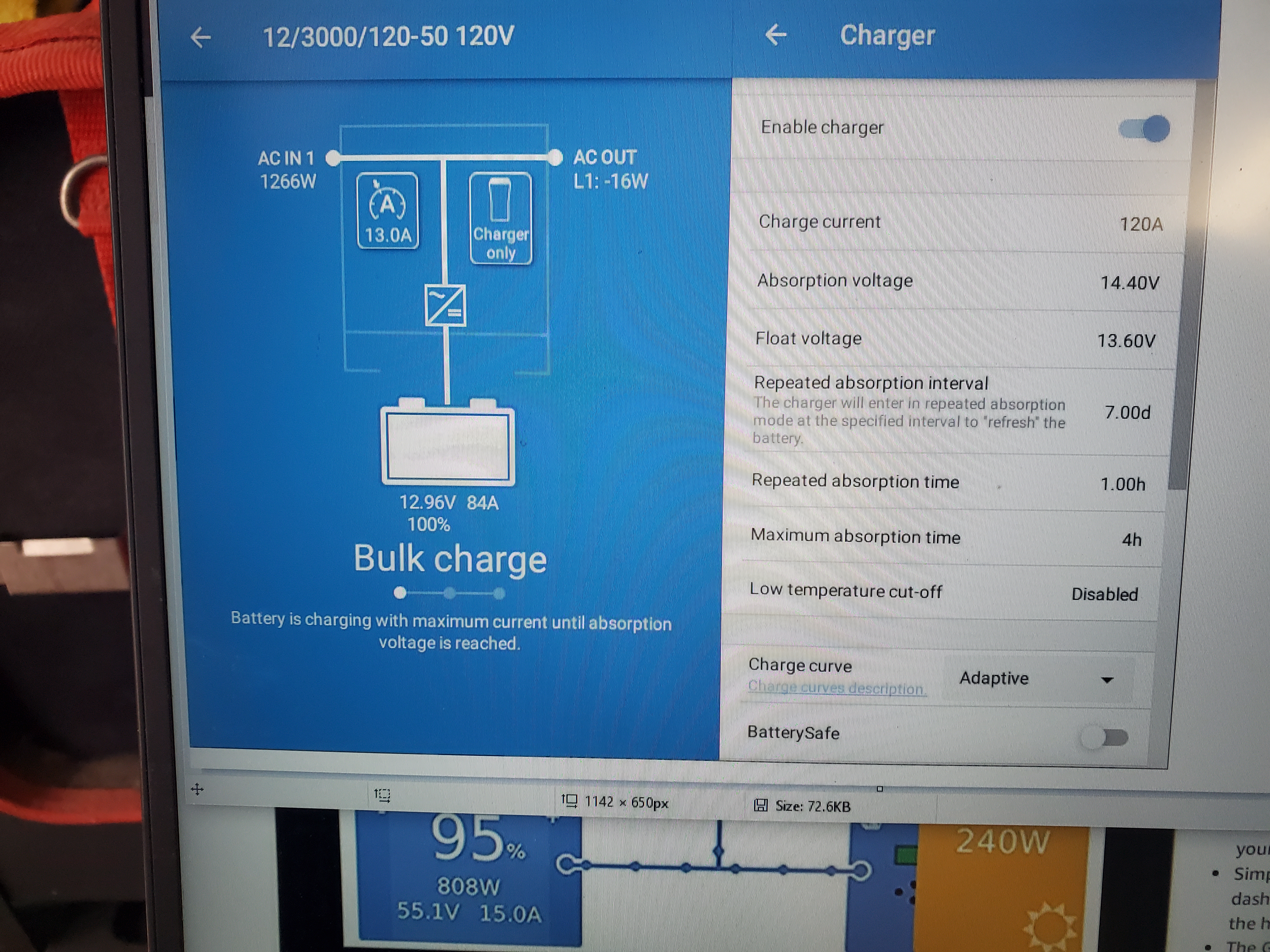
The customer went to a local Victron shop (and also got an MK3) and we're starting to get a better idea of what's going on here. Somehow the Voltage the inverter is sensing is a full 1 Volt less than the actual battery Voltage measured at the inverter's terminals. So, a setting of 14.4V for charging would mean the inverter actually runs the Voltage up to 15.4V, and that will most definitely kick in the over-Voltage protection on any lithium-ion battery with a BMS. Please have a look at the pictures illustrating this.

Has anyone seen this before? The inverter has been updated to the latest firmware, just in case. Battery temp sensor is disconnected.

-Rob-20211208-134516.jpg20211208-134536.jpg


6 comments
2 |3000

Up to 8 attachments (including images) can be used with a maximum of 190.8 MiB each and 286.6 MiB total.

nebulight avatar image nebulight commented ·
You could be getting voltage drop at the multi in which the v-sense wires could compensate for. I see you have copper bars off the linx, they look pretty narrow so this might be your issue. How thick are they?
0 Likes 0 ·
veronique avatar image veronique nebulight commented ·
Hi!

They are about 1/4" thick! The Victron distributor I bought it from had them made for the Lynx's purpose, for some reasons, we don't have access to the adapters sold by Victron in Canada (I've been told)!

Thanks for so many of you wanting to figure this out! :)!


0 Likes 0 ·
nebulight avatar image nebulight veronique commented ·

Rob's pictures didn't load for me before. It's showing 13.99v on the terminals but 12.95 on the multi. And both of these were under load when the photos were taken? If so, I've never seen this before on a multi. Have you tried to hook up vsense wires? There is nothing to configure, you simply put two small gauge wires in there and hook them up to the battery.


I'd also check for voltage drop across your main battery fuse under load. That's an ANL fuse so you should get around a 50-100mv drop. That looks to be a name brand busman fuse, but who knows these days. I just helped some people with cheap fuses that was causing similar problems, but in the other direction with their water heater. Turned out the voltage drop was being caused by a knock off fuse.

Also check all your connections are tight, everywhere.


0 Likes 0 ·
Show more comments
amgrumpy avatar image
amgrumpy answered ·

Hi,since this thread and microwave one i bought a mk3 also,to learn and noticed charge curve on my easysolar is set to fixed, unless you've been informed otherwise this is best for lifepo4 then you can set a fixed absorption time,ie recommended by battleborn of 30 minutes per 100ah so 2hrs, battleborn also uses fixed charge setting.Something to help you get one step closer to happy.

Good luck.cant help with voltage readings

2 |3000

Up to 8 attachments (including images) can be used with a maximum of 190.8 MiB each and 286.6 MiB total.

ystwyth1 avatar image
ystwyth1 answered ·

Hello, i have finally found a problem that matches mine.


I have gone from a Easy Solar with AGM that just worked and behaved, to upgrading to Lifepo4 and a shunt so now, Easy solar 24/3000/ with smart shunt 500A, now this is where the problem starts after the upgrade. i am seeing the same problem i have 4 Lifepo4 drop ins and i am seeing at absorption 28.4 and the battery's are going up to 15.56 and going in to overvoltage protection kicking out the absorption. every thing looks fine in bulk charge the mid points are with in 0.1 up until abs. i am seeing a 1.5 ish volt difference. about 15 minuets in to abs the problems starts.


the Easy Solar and the shunt and the seem to see 26v but the battery's are 27v i have run a multimeter over the setup the voltage is the same with in + - 0.3v before the shunt and after the shunt are the same as the batteries i have checked the fuse in the mid point connections of the shunt and are 1a not 100ma. i cannot work put why the multi is 1v out but its casing problems.


so as a work round for the time being would it be worth dropping the abs and float down a volt to compensate?


look forwards to seeing more input on this as its baffling me


Paul

1 comment
2 |3000

Up to 8 attachments (including images) can be used with a maximum of 190.8 MiB each and 286.6 MiB total.

nickdb avatar image nickdb ♦♦ commented ·

You are going to have to provide a lot more detail about your setup. Because you see similar symptoms does not mean you have the same issue.

Why are you using a shunt with with lithium batteries?

Are you using a BMS?

Are your batteries on the supported list?

Have you followed any of the generic steps in the setup docs on the battery compatibility list (setting up DVCC etc)?

https://www.victronenergy.com/live/battery_compatibility:start

If there is no intelligence managing the batteries, you're in for some challenges. The manufacturer really should provide you with some guidance.


0 Likes 0 ·