Hi,
I’ve been working on the schematic for my conversion build but I am having a tough time convincing myself it’s safe when it comes to the inverter/charger. I’ve read several manuals, guides, and posts in this forum (and other forums) regarding this topic, but none of them give consistent information that I find to be trustworthy. If I missed the answer to this, I apologize.
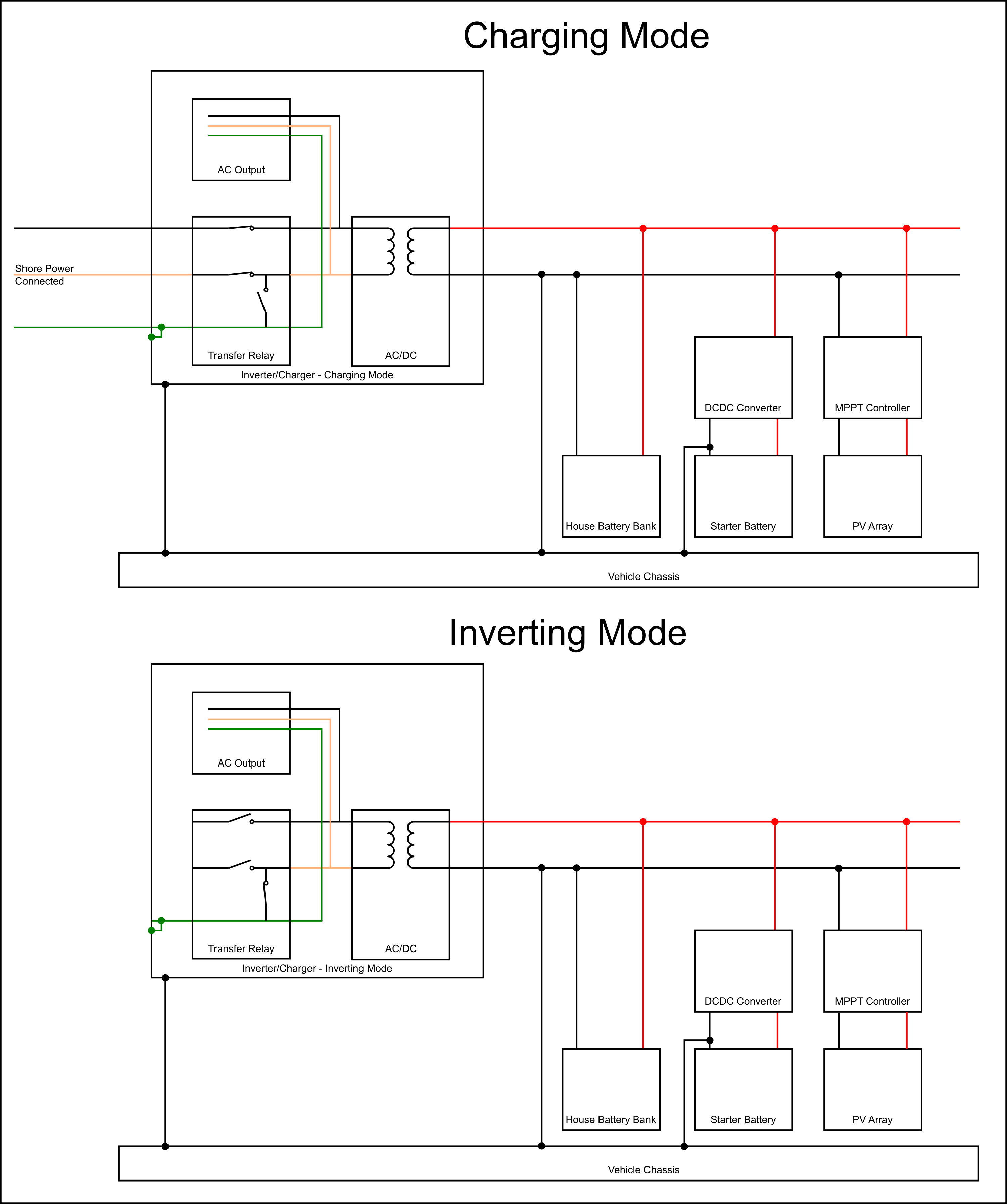
The metal enclosure of the inverter/charger should be tied to the vehicle chassis. Assuming the inverter/charger contains an automatic transfer switch that connects the Neutral to the metal enclosure (chassis) when no shore power is available, a TN-S earthing system is created. This part is rather straight forward, but I am concerned about the fact that the negative terminal of the vehicle’s starter battery and the negative terminal of the house battery are also tied to the chassis. Since the Neutral is connected to the chassis, the high voltage AC is no longer isolated from the low voltage DC circuits, which I believe creates a safety issue on the low voltage side as the 12Vdc circuits are much more accessible due to the number of loads that run directly off it.
Here is a simple schematic that shows the lack of isolation (in inverting mode).

This is based off a system schematic readily available from Victron:
https://www.victronenergy.com/upload/documents/DS-Lucians-Victron-Van-Automotive-Full.pdf
Are my concerns valid? Or am I overthinking this?
Any advice would be greatly appreciated. By the way, I am in the US.
Thanks,
Phillip
