question

ttmott avatar image
ttmott asked

Terminating inverting during engine cranking

We are in the process of adding two 12/3000/120-50 Multiplus inverters set up in a US split phase configuration (120-0-120) with a CCGX controller to our boat. The battery bank will be 8 each 100AH LiFePo4's with each having integrated BMS all in parallel. The boat's generator (14.7KW) and shore power will also be integrated as well as the engines' alternators. Each battery can tolerate 200 AMP current discharge for up to 30 seconds. We will be using this battery bank for engine cranking as well as for the House; engine cranking requires 1400CCA for up to 10 seconds for each engine.. During engine cranking it will be necessary to suspend any AC inverting the Multiplus' are performing. Can the analog/digital I/O port on the Multiplus be tied to the engine start solenoids to detect engine cranking and suspend inverting? If so how to configure? If not how can this be done autonomously ?

Thanks you for the help!

MultiPlus Quattro Inverter Charger
2 |3000

Up to 8 attachments (including images) can be used with a maximum of 190.8 MiB each and 286.6 MiB total.

6 Answers
dwmarine avatar image
dwmarine answered ·

I'm not sure of an easy way to do this myself.

You may find the voltage spikes from engine cranking will play havoc with your electronics if they are both on the same battery bank, hence many manufacturers specifically ask for a dedicated start bank.

How do you propose to start your engines or generator if the house battery bank is low or flat?

It might be better to have a separate engine start battery, (one battery can do both engines) and link this to your other batteries via a VSR with start interlock.

The Victron units have a trickle charge output that you could use to keep a start battery topped up.


1 comment
2 |3000

Up to 8 attachments (including images) can be used with a maximum of 190.8 MiB each and 286.6 MiB total.

ttmott avatar image ttmott commented ·

There are no "voltage spikes" during cranking. There is a voltage sag depending upon cable lengths and conductor sizing.

When you look at the actual Amp Hours consumed during cranking, it ends up being rather incidental even at the largest current demands due to the short time (15 or less seconds). The lithium batteries are so good at maintaining peak voltage that as long as they can support the current (1400 amps) they will work perfectly for starting currents even if depleted to as low as 80% DOD.

The issue we are having if the engine is cranking at 1400 amps and the inverters are pumping out AC power to the air conditioners and other loads the battery BMS can possibly trip; consequently, we need to terminate the inverting during cranking.

The generator will have an AGS integrated and will be set to come on at 70% DOD and begin battery recharge. Plus, the generator will have it's own single Group 27 AGM battery.

0 Likes 0 ·
Paul B avatar image
Paul B answered ·

Even if you could trigger the inverter to shut down you need to do this before you start cranking not at the same time as the starter engages. however if this is ok with you then

you could connect a relay N/C across the remote switch on the inverter, and then as soon as the engine crankes the inverter will simply turn off then when cranking finishes it will turn back on.


all AC would then be off while you are cranking

2 comments
2 |3000

Up to 8 attachments (including images) can be used with a maximum of 190.8 MiB each and 286.6 MiB total.

boekel avatar image boekel ♦ commented ·

As far as I know the remote switch doesn't work when connected to CCGX (disclaimer: haven't tried this myself)

You could use the emergency switch assistant for this, as it reacts immediately.

But if the engine starting has such a big effect on the batteries, I'd use a separate starting battery...(I normally use a small optima AGM for this)

0 Likes 0 ·
ttmott avatar image ttmott boekel ♦ commented ·

How does the emergency switch assistant get accessed? From that I/O port in the Multiplus?

0 Likes 0 ·
ripper avatar image
ripper answered ·

I would doublecheck the actual cranking amps that are goibg to the starter motor. CCA sounds like read off the original lead acid battery and means something very specific that you are likely to not encounter in a marine application, has nothing to do with the actual amps drawn of the starter motor and drawing 1400A would be one helluva starter motor, maybe two but who has that. Highest I have seen is around the 500A at 20V ( it is a 24V system) while engaging the starter motor for the briefest instant of a 9 liter Scania diesel engine. Dry cranking till she fired was "only" 280A at then 21V. Since Lixx wont drop that far in voltage, the amps will be even lower. Chances are, you might be able to not worry about it at all.


Is there any automatic delay while starting? Like glow plugs? I would rig above mentioned relay to the keyswitch. Also air cons dont like being cut off like that. The gas in the compressor might become fluid at a stand still and it hydro locks then when instantly restarted. Same with a compressor fridge.

13 comments
2 |3000

Up to 8 attachments (including images) can be used with a maximum of 190.8 MiB each and 286.6 MiB total.

ttmott avatar image ttmott commented ·

Yes the cranking amperage is very high. The engines are Cummins QSM11's 660HP each. They are also 12VDC. The requirement for 1400 amps for each engine is from the Cummins engine installation literature. There is no delay; press the start button and they crank over.

The boat's electrical systems are designed to all shut down then restart as this is what happens when transfer from shore power to generator every time.

Victron states there is a port in the Multi's that can be used to integrate an external BMS and I was hoping this port is used to halt charging and/or inverting upon a BMS issue and by using the 12VDC engine start voltage used to actuate the start relays I could do the same..

And BTW, I cannot find anything in the Victron Literature about the port other than it's there and can be used for several different things.

0 Likes 0 ·
ripper avatar image ripper ttmott commented ·

https://www.sbmar.com/engine-info/cummins-qsm11-specifications/


I am not convinced. You went from CCA to actual amps in your answers. In above link they also only talk about CCA which is a rating that has nothing to do with amps flowing out of a Lixx battery during start up. Unfortunality I cannot help you on the other issue

0 Likes 0 ·
ttmott avatar image ttmott ripper commented ·

My bad - actually recommended minimum battery capacity is 1800CCA.

Regardless, We still want to suspend any inverting during engine cranking.

Thanks!

0 Likes 0 ·
murph avatar image murph ttmott commented ·

CCA is not the actual current drawn while continuously cranking, despite being "cold cranking amps". It's a spec for how low the starter bank may sag under extreme load at low environmental temperature. Engine manufacturers typically specify a starter bank CCA which is many times greater than the actual current drawn.

For example, the Perkins 1106 (aka Cat C7.1) has a 4kW starter, so nominal 333A current at 12V, but specifies a 900 CCA (SAE J537) starter bank down to 5°C, or 2x700 CCA down to -25°C.

Cummins are telling you absolutely nothing about the cranking current with their CCA number. They are giving you a battery spec for performance under a theoretical extreme load at very low temperature.

0 Likes 0 ·
murph avatar image murph ttmott commented ·

Continued from above, as it wouldn't post despite being within the comment size limit.

Getting into personal preferences / opinion now. I'd just have a dedicated starter bank of 4 (maybe even 6 if strong dual startup is needed in freezing conditions) good AGMs with suitable CCA rating, shared between the engines. The expensive LFPs can do heavy cranking at 2C output, but it's going to prematurely age them. AGMs should handle it much better.

0 Likes 0 ·
ttmott avatar image ttmott murph commented ·

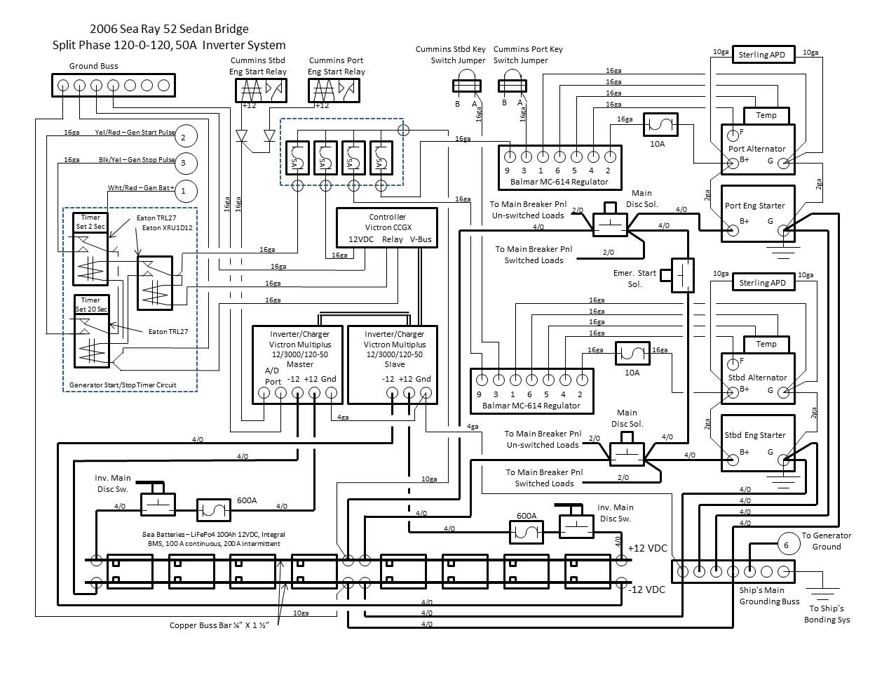
Understand and thank you. Our electrical engineers who are doing the design have been working with Battle Born batteries and they have concluded no adverse affect to the batteries which in total will be significantly less than 2C during cranking (10 seconds or less) provided inverter loads are suspended. Baseline is 8ea (may grow to 10) 100AH batteries which can support 100 amps continuous and 200 amps for 30 seconds each without detrimental effects. This is our baseline schematic (still in work however).


0 Likes 0 ·
inverter-plan.jpg (188.4 KiB)
murph avatar image murph ttmott commented ·

And a little "what if?". You've been anchored near a narrow shipping channel. Suddenly the anchor alarm on the nav console goes off, as you drag or lose the anchor. The combination of wind & current is taking you into the channel, as cargo ships approach from 0.5nm @ 8kn in both directions, both with COLREGs lights or shapes indicating they have restricted ability to maneuver or are constrained by draft. You hit the starter, and the BMS goes into HAL 9000 mode, refusing to give you amps. You have less than 5 minutes to avoid being featured on the evening news.

1 Like 1 ·
ttmott avatar image ttmott murph commented ·

Classic! So, this was the main reason to have integrated BMS in each battery so if one goes "HAL 9000" we will still be good to go..... Also the battery manuf. is recommending having the AGS start recharge NLT 70% DOD. The generator BTW will have it's own AGM start battery. Shame on me for setting a single anchor with such risk.....

0 Likes 0 ·
murph avatar image murph ttmott commented ·

You can thank my Yachtmaster practical examiner for that. He only gave me one ship, but put me directly in its path (at approx 0.5nm) before allowing me on deck to deal with it.

0 Likes 0 ·
ttmott avatar image ttmott murph commented ·

So you have what - 3 minutes to not only clear but also get out of the prop wash??? And?

0 Likes 0 ·
Show more comments
murph avatar image murph ttmott commented ·

Ok, good luck with it. A couple of things to consider. Get the exact model of starter from Cummins and the spec sheet from them or the starter manufacturer. Let your electrical engineers digest that info, particularly the initial current spike needed to get the engine moving when cold. Don't forget the current for the engine ECUs, pumps, injection, heaters, etc (modern diesels can have a surprisingly high current draw for that stuff, not sure about those particular engines). I would probably consider an interlock to prevent cranking both simultaneously, if that would push the limit.

0 Likes 0 ·
ttmott avatar image ttmott murph commented ·

Yes as well as the other parasitic DC loads like lighting and navigation equipment. We have resolved to measure actual current during cranking due to the many variables. I'm leaving it up to the EE's to get it right.... And, FYI, these engines have no heaters however they are electronic and there are voltage/current requirements for those systems.

0 Likes 0 ·
Rob Fijn avatar image
Rob Fijn answered ·

Hello ttmott, this is one way to do it, but it is manual way to do it.


The VE.bus BMS could also be a way. As you can use a relay as ON/OFF of the BMS and this will send a signal over the VE.bus to switch on Inverting.

regards,


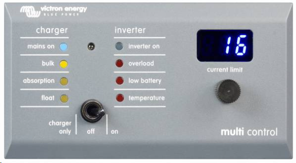
1551899645626.png (2.1 KiB)
1551899675216.png (249.8 KiB)
2 comments
2 |3000

Up to 8 attachments (including images) can be used with a maximum of 190.8 MiB each and 286.6 MiB total.

ttmott avatar image ttmott commented ·

I'll look into the VE bus BMS

So, that port on the Multi/Quatro called Analog/Digitial I/O; nobody has used it?

0 Likes 0 ·
Rob Fijn avatar image Rob Fijn ttmott commented ·

Hello ttmott, I do this with the panel above, but as said manually.

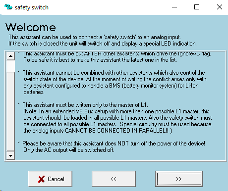
The assistant Safety Switch can do this also for you, but it switch OFF the AC output. At least this will take off the load on the battery for you.

I can think of a rely that can give the close-signal to the Multi digital input


0 Likes 0 ·
1551922094002.png (11.1 KiB)
ttmott avatar image
ttmott answered ·

Thank you Rob! From what I can determine the digital input is non-isolated and limited to 5VDC; is that correct?

1 comment
2 |3000

Up to 8 attachments (including images) can be used with a maximum of 190.8 MiB each and 286.6 MiB total.

boekel avatar image boekel ♦ commented ·

yes you need a 'dry contact' (a relay) to safely connect to the input.

0 Likes 0 ·
ttmott avatar image
ttmott answered ·

Update and Closure - the engineers have determined that there are certain risks using the Lithium battery bank for starting - they all admit it shouldn't be a problem however to simplify the entire system they are recommending installing a couple of Maxwell Starting Modules which are supercapacitor banks and will manage the high current cranking requirement. So, essentially the Lithium batteries will supply the inverter/chargers and all other house and navigation loads; the Lithium batteries and inverter/charters will also charge the supercapacitors.

Thanks everyone for the help and suggestions!

2 |3000

Up to 8 attachments (including images) can be used with a maximum of 190.8 MiB each and 286.6 MiB total.