question

mvader (Victron Energy) avatar image
mvader (Victron Energy) asked

Venus OS v2.80~21 available for testing

Good evening, to most, and otherwise good day!

UPDATE Sept 27th: v2.80~21 is now available. Only one addition, the wireless temp sensors are now supported.

Its time for a new test version of v2.80. In case you don't know what this message is about, please start with reading this link.

The highlights of v2.80 are the new AC Load monitoring, the new DC metering function which now are visible in the Device List in the UI, and also new since this version are various improvements to the HTML5 MFD App, including the addition of translations.

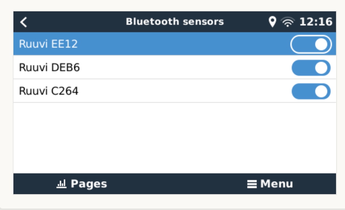
Per ~21, the Ruuvi Tag wireless temperature sensors


What to test?

Same as before: the new features I mentioned just now. As well as, just like announced previously, basically everything: there are several major changes in v2.80, which can each make things break in unexpected places. The first change is that the used Python version has been updated from 2.7 to 3. Also the Open Embedded release was upgraded from Zeus to Dunfell, and lastly we changed to a read-only rootfs. All combined this means that (a) lots of tools and packages used will have changed to a newer version, and (b) lots of Victron code has been changed to be compatible with Python 3.


How to post an issue?

Preferably all issues are organised as answers to this question. One answer per issue. So first check the existing threads. If you have the same as someone else already reported, welcome to add a comment saying "me too". And preferably some more details. And in case its not listed yet, add a new Answer. Note that Answers and Comments are two different things here on community.

Lastly, if possible please revert to v2.73, to double check if the issue you're seeing was present there as well. Regressions require a different treatment than other issues and bugs, and one of the first things that needs doing in triaging a report is distinguishing between the two.


The plan for v2.80

Development and testing will continue for quite a while; we won't make September anymore. So now, with a bit a luck, somewhere in October this year. The main new feature that needs further completion is DC metering for both loads and production (alternator or hydro or wind for example).


Changes below.

For now, all the best and have a good weekend,


Matthijs Vader


Changes since previous test version, which was v2.80~17:

Sensors:

  • Add support for the Ruuvi Wireless temperature sensors. Besides temperature, also humidity and atmospheric pressure are supported. Uses Bluetooth, and works on the Cerbo GX (only). Possibly it also works on other GX devices if a compatible USB/BLE dongle is used - but thats not something we’re looking into at the moment.

HTML5 MFD App

  • Add lock button that helps prevent accidental button presses like "Start generator" or "Multi Off".
  • Add Dutch, Chinese, French, German and Italian to thelanguages.
  • Add a placeholder & message in case no data is present.
  • Add 3A button to the input limit selector.
  • Hide 3rd phase in case of a split-phase system.
  • Fix keyboard buttons not working in Remote Console.


Inverter RS

  • remove support when connected on VE.Direct. As emailed publicly, from v2.80 onwards the Inverter RS, and in the future also the Multi RS, must be connected using the VE.Can port. Connecting them with the VE.Direct port to a GX device no longer works. MPPT RS still works on both, and will remain working on both.


DC Monitor (the new feature for the BMV-712 and SmartShunt already introduced in an earlier v2.80 test version)

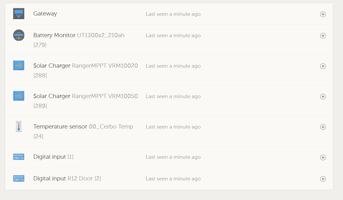
  • add entries into the Device-list


DVCC

  • Force good settings for BMZ ESS Batteries: DVCC=ON, SVS=Off, STS=Off
  • Force-enable SVS for the Lynx Smart BMS


ModbusTCP

  • Solar chargers and Inverter RS: remove registers for per-tracker current, and add registers for per-tracker power.
  • Add registers for DC Monitor types: alternator, dcsource, dcload, dcsystem and fuelcell


VRM Portal

  • Fix problem with slower data updates on the portal and higher CPU use on the GX device. Issue was introduced earlier during v2.80 development. Thank you @gnagflow , @N-DEE , @matthiasroetzer and probably more help reporting that.
  • Remove logging of Solar PV current. Instead, only PV Array Power and PV Array Voltage is logged.


Other:

  • Bluetooth connection for VictronConnect: fix 000000 pin code, this was broken earlier in v2.80 development. Thank you Stefanie for point this out!
  • Add Easter Island and Christmas Island timezone options
  • Fix default values for AC input 1 and AC input two. Now they are Gird and Generator again, instead defaulting to "AC input not available". This was broken in Venus OS v2.60.
  • Add names for various new model inverter/chargers.


Internal/developer:

  • In various places we removed the solar charger PV array current (Amps) values. From D-Bus, MQTT, VRM Logger, Modbus-TCP, Node-red. And instead made sure that Power and Voltage is available for each array. This reduces unnecessary D-Bus traffic and as such optimises the maximum number of installable Solar Chargers. Note that this might break existing MQTT, ModbusTCP or similar integrations. Which is a pity ofcourse, though we do think its better like this going forward. Any UI or integration can ofcourse itself calculate the current by dividing the power by the voltage. Just like the GUI in Venus OS itself does now.


Complete v2.80 change log, compared to v2.73:

No time for that now, I'll make that later (again).


Known issues

  • When configured as a DC Monitor (alternator, and so forth), the information from a BMV-712 or SmartShunt is not transmitted onto NMEA2000, ie its not supported by NMEA2000-out. The exception is when configured as Solar charger.
Venus OS
19 comments
2 |3000

Up to 8 attachments (including images) can be used with a maximum of 190.8 MiB each and 286.6 MiB total.

mvader (Victron Energy) avatar image mvader (Victron Energy) ♦♦ commented ·
Hi all, short update: ~21 is now available, adds the RuuviTag temperature sensors
0 Likes 0 ·
Show more comments
19 Answers
Paul B avatar image
Paul B answered ·

Just a note and its not Victron Problem I think - but Kevin Windrem add on system did not survive the upgrade.

1 comment
2 |3000

Up to 8 attachments (including images) can be used with a maximum of 190.8 MiB each and 286.6 MiB total.

Kevin Windrem avatar image Kevin Windrem commented ·

This is not a v2.80~19 issue. A file that GuiMods changes needed to be updated. Fixed now.


If you have automatic package updates enabled, you should get the new version (v3.2). If not, you will need to run /data/SetupHelper/setup and choose G then O.


If you have not updated to v2.80~19 yet, enable package updates from the Display menu first to save yourself the hassle of command line stuff.

0 Likes 0 ·
Paul B avatar image
Paul B answered ·

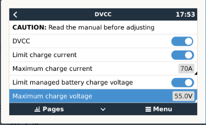
The DVCC Max Charge Voltage does NOT seem to control The multiplus II (Early version) charge voltage (its not just the Multiplus II as well and I am sure one site I have tried it with It is not working on standard multiplus units with CCGX with release software), The max current control is working fine. This Max Charge Voltage has not worked even for earlier versionsas well - Unless I am miss interpreting what it does.


Any way my system is currently outputting its set voltage in the Multiplus being 56.00 and is not being controlled back to 55v as per the DVCC indication. Fw 487 on the Multiplus II

1632567253518.png


1632567253518.png (30.5 KiB)
1 comment
2 |3000

Up to 8 attachments (including images) can be used with a maximum of 190.8 MiB each and 286.6 MiB total.

mvader (Victron Energy) avatar image mvader (Victron Energy) ♦♦ commented ·
Hi, what battery do you have in that system, a managed one, ie a canbusbattery?


because thats what this setting is for, maximizing the voltage that results from a canbus-connected battery.


the setting is not intented do, and also will not, override charge voltages in a system thats not battery controlled

0 Likes 0 ·
seb71 avatar image
seb71 answered ·

In various places we removed the solar charger PV array current (Amps) values. From D-Bus, MQTT, VRM Logger, Modbus-TCP, Node-red. And instead made sure that Power and Voltage is available for each array. This reduces unnecessary D-Bus traffic and as such optimises the maximum number of installable Solar Chargers.

PV current was much more useful than PV voltage in VRM (but I would rather have both).

1 comment
2 |3000

Up to 8 attachments (including images) can be used with a maximum of 190.8 MiB each and 286.6 MiB total.

mvader (Victron Energy) avatar image mvader (Victron Energy) ♦♦ commented ·
Hi, yes we’ll make the advanced graph work again, its a simple division of power by voltage.
0 Likes 0 ·
jwfrary avatar image
jwfrary answered ·

Firstly thanks for your work on this latest iteration, big leaps forward.

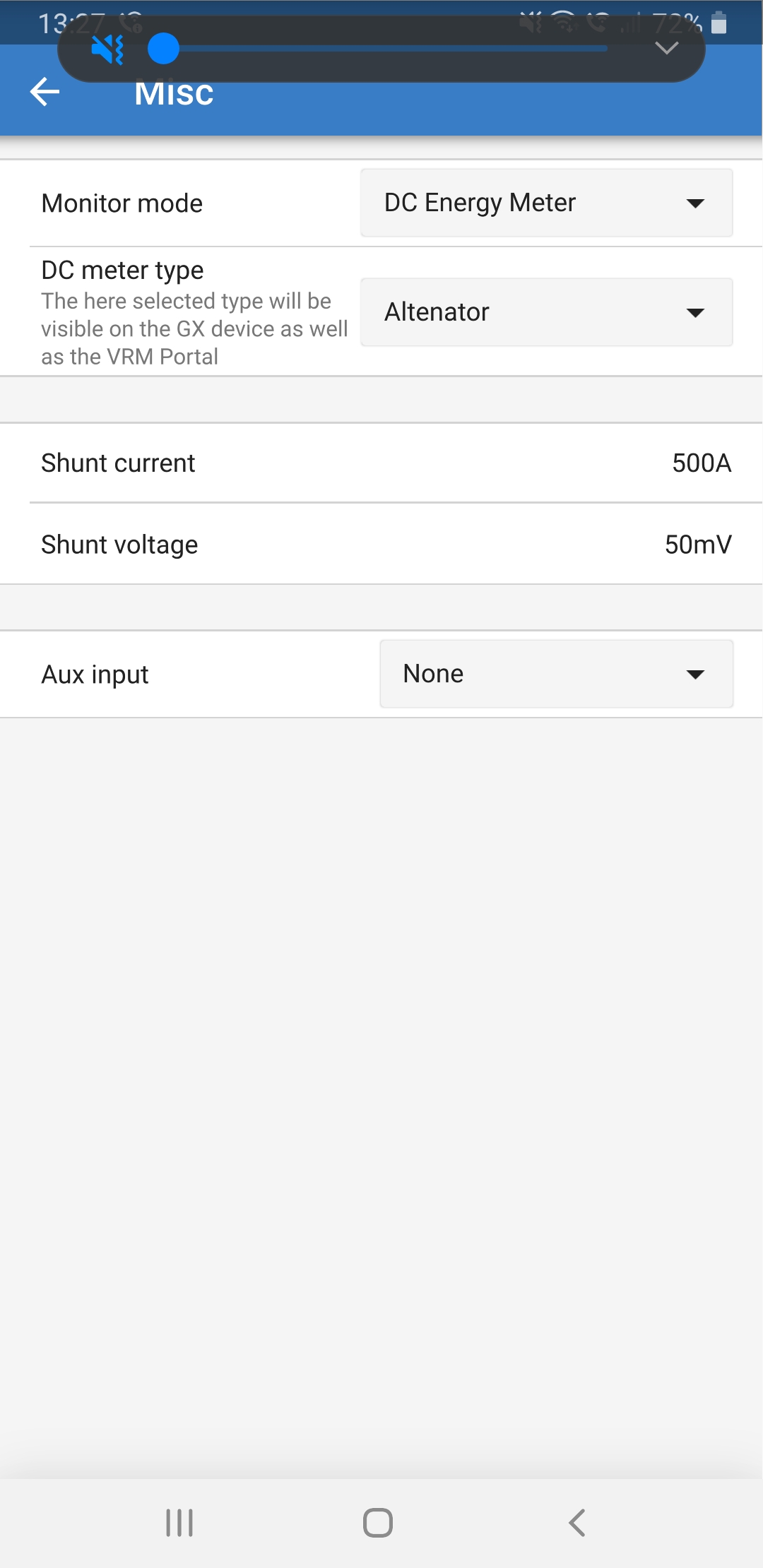
This is running stable on my system, all I noticed was in the BMV 712 firmware when using as a dc load meter alternator is missing an r in the spelling.

Another thought, it might be a useful addition to be able to set the temp input as the alternator temperature in this application!?

screenshot-20210926-132759.jpg


7 comments
2 |3000

Up to 8 attachments (including images) can be used with a maximum of 190.8 MiB each and 286.6 MiB total.

mvader (Victron Energy) avatar image mvader (Victron Energy) ♦♦ commented ·
Hi, thank you for the encouragement. Typo


temperature: I’ll look into that, since the sensor needs wiring to battery positive, I’m not so sure wether encouraging to use it on an alternator will work. Also the range of measurable temperature might be an issue.

0 Likes 0 ·
jwfrary avatar image jwfrary mvader (Victron Energy) ♦♦ commented ·

Ah yes the battery positive for the sensor makes it difficult. I have 1 wire sensors strapped to ours already gives some idea of what's going on.

0 Likes 0 ·
Paul B avatar image Paul B mvader (Victron Energy) ♦♦ commented ·

Hi, Could I ask for a double check here RE above coment (since the sensor needs wiring to battery positive )

Reason is - as I have put the Multiplus temp sensor onto the inverters case and its reading temp fine as far as I am aware (ie batery temp is showing the Multiplus inverter Temp) (as this site has LiFePo4 the temp compensation is not used as far as I know)

0 Likes 0 ·
mvader (Victron Energy) avatar image mvader (Victron Energy) ♦♦ Paul B commented ·
SmartShunt and BMV-712 use a different sensor that the MultiPlus. And their sensor needs wiring to batterypositive. See SmartShunt manual.


Also there is the max temperature issue. We checked, and max temperature measured is 104C. I don't think thats enough for an alternator.

So we could ofcourse look further into it, possibly make a different temp sensor, check the voltage divider on the SmartShunt, etc etc; but for now we're not going to do that, I'm sorry.

So answer: don't use that temp sensor to measure alternator temp.

0 Likes 0 ·
Paul B avatar image Paul B mvader (Victron Energy) ♦♦ commented ·
Sorry but you seem to have miss read my question, as I was referring to the NEED to have it connected to a positive battery source , as currently I have it connected to the Multiplus Inveters case and its working fine, this infers, that there is no requirement physically to have it connected to a positive battery source ????
0 Likes 0 ·
mvader (Victron Energy) avatar image mvader (Victron Energy) ♦♦ Paul B commented ·
Hi, did you check the manual already? Pls do. The batt positive connection and temp sense are one and the same thing
0 Likes 0 ·
jwfrary avatar image jwfrary mvader (Victron Energy) ♦♦ commented ·
104 is certainly not enough inside the alt but maybe on the outside!? On the b+ terminal. I'll get the flir out and see....
0 Likes 0 ·
Kevin Windrem avatar image
Kevin Windrem answered ·

BUG: PV Power is not being reported.

I am displaying PV voltage and current in my GuiMods PV tiles. When I went to recode to use power instead of current (which is removed in this version of Venus OS, I noticed it is not a parameter at least for my BlueSolar 100 | 30. All that's reported is PV/V now.

3 comments
2 |3000

Up to 8 attachments (including images) can be used with a maximum of 190.8 MiB each and 286.6 MiB total.

mvader (Victron Energy) avatar image mvader (Victron Energy) ♦♦ commented ·
Hi Kevin, the power is a in a bit unexpected place, its /Yield/Power.


I checked your system and the power is there. You got me worried there for a moment, ie "how could we have missed that!?" .

;o)

0 Likes 0 ·
Kevin Windrem avatar image Kevin Windrem mvader (Victron Energy) ♦♦ commented ·
OK. Got it. The unexpected place is what caused me to miss it. Thanks.


0 Likes 0 ·
Kevin Windrem avatar image Kevin Windrem commented ·

GuiMods v3.3 uses power/voltage to calculate PV charger current if current value is not present.

https://github.com/kwindrem/GuiMods

0 Likes 0 ·
kris avatar image
kris answered ·

In this release, the connection to the HTML5 MFD is very long or no connection.

3 comments
2 |3000

Up to 8 attachments (including images) can be used with a maximum of 190.8 MiB each and 286.6 MiB total.

mvader (Victron Energy) avatar image mvader (Victron Energy) ♦♦ commented ·
Hi Kris, can you describe your setup a bit? Is it connected to vrm?


And how do you access the html5 app? On an MFD? Or?

And using wifi? Or LAN?

Thanks!

0 Likes 0 ·
kris avatar image kris mvader (Victron Energy) ♦♦ commented ·

Configuration 2 pieces MPPT (VE.direct), MultiPlus (Ve.Bus), 712 i Smart shunt (VE.direct), BMS REC (Ve.Can), IP43 new version (VE.direct) Cerbo, Garmin 8412 Furuno TZ3 ( LAN)

I am connected to VRM.

0 Likes 0 ·
kris avatar image kris mvader (Victron Energy) ♦♦ commented ·

I reloaded the software again and the connection is good (fast)

0 Likes 0 ·
seb71 avatar image
seb71 answered ·

I updated my Cerbo from v2.80~19 to this new v2.80~21 a few minutes ago.


At first boot Remote Console partially loaded and then I lost connection (over Wi-Fi).


I connected a LAN cable and I could access my Cerbo with Remote Console, but it was very sluggish.


I performed a reboot (from Cerbo's menu) and after that I could access it more or less normally using Remote Console (including via Wi-Fi) for a few minutes. Then Wi-Fi failed again. And over LAN it was again very sluggish.


I power cycled the Cerbo - same sluggish Remote Console (over LAN/UTP cable).

I booted back into v2.80~19.

2 |3000

Up to 8 attachments (including images) can be used with a maximum of 190.8 MiB each and 286.6 MiB total.

Steve Preston avatar image
Steve Preston answered ·

Will there be any plans, at some later date, to incorporate the motion input from the Ruuvi sensors since that is part of their configuration? That would be an excellent theft detection input for many types of installations.
"Sensors:

  • Add support for the Ruuvi Wireless temperature sensors. Besides temperature, also humidity and atmospheric pressure are supported."
1 comment
2 |3000

Up to 8 attachments (including images) can be used with a maximum of 190.8 MiB each and 286.6 MiB total.

mvader (Victron Energy) avatar image mvader (Victron Energy) ♦♦ commented ·
Hi @Ranger Rocko , perhaps some day; but not in immediate future.
0 Likes 0 ·
dsfas9 avatar image
dsfas9 answered ·

I am having issues with ~21, wifi signal is a lot weaker than in ~17 and everything loads a lot slower. Cerbo and wifi AP are 3 feet away and are physically secured in place.

2 comments
2 |3000

Up to 8 attachments (including images) can be used with a maximum of 190.8 MiB each and 286.6 MiB total.

mvader (Victron Energy) avatar image mvader (Victron Energy) ♦♦ commented ·
Hi @dsfas9 , thats most likely similar to the issue that @Seb71 reported. With help of Seb we analysed a bit more; and its due to the addition of the reading of, listening for-, wireless


in the next beta there is a switch, that allows disabling them. Disabled by default.

Looks like its just a fact: some wifi connections get worse by enabling this. Not all. Wifi and Bluetooth do share the same radio.

0 Likes 0 ·
Paul B avatar image Paul B mvader (Victron Energy) ♦♦ commented ·
Have had this problem on two on my test sites one is really bad and one that upgraded from 2.73 to 2.80~21 had good wifi then really bad wifi after the upgrade then after a reboot it was fine
0 Likes 0 ·
Kevin Windrem avatar image
Kevin Windrem answered ·

I can confirm the Wi-Fi connection on my Cerbo is significantly impacted by v2.80. Response is fine with v2.73 but not with v2.80~21. I don't recall this problem with earlier versions of v2.80 but could be wrong. (Ethernet is unaffected, just Wi-Fi.)

I also feel overall responsiveness is slower (looking at the Touch 70) also. For example, discovery of a VE.Bus inverter seems to take longer.

2 |3000

Up to 8 attachments (including images) can be used with a maximum of 190.8 MiB each and 286.6 MiB total.

kris avatar image
kris answered ·

After changing the function of BMV-712 smart DC battery monitor to DC monitor, the device is not visible in the N2K network.

3 comments
2 |3000

Up to 8 attachments (including images) can be used with a maximum of 190.8 MiB each and 286.6 MiB total.

mvader (Victron Energy) avatar image mvader (Victron Energy) ♦♦ commented ·

Hi @Kris thank you. We'll look into that.

0 Likes 0 ·
mvader (Victron Energy) avatar image mvader (Victron Energy) ♦♦ mvader (Victron Energy) ♦♦ commented ·
ps. it might take a while before we get round to add them (alternator, source, and so forth) to NMEA2000-out. And note that when configured to monitor a solar charger that it *does* already work on NMEA2000-out. At least I'd expect it to work; not tested.
0 Likes 0 ·
kris avatar image kris mvader (Victron Energy) ♦♦ commented ·

When set as a solar charger, it is visible in the N2K checked network.


Can't see, I will set up a DC monitor in MFD HTML5, if I set it up as a solar charger, it can be seen.


I will ask how many Ruuvi sensors we can connect, one works well, in addition I use 3 temperature inputs from Cerbo with wired sensors ..

0 Likes 0 ·
kris avatar image
kris answered ·

Another topic when I use garmina 19 garmin in n2k network is visible through Cerbo for VRM positioning, when I use Furuno SCX-20 satellite compass it is not possible to use VRM installation positioning.

The PGNs responsible for the gps data are standard, the remaining PGNs are related to other parameters, where is the problem?

1 NMEA2000 port

Input: 059392/904, 060160/416/928, 061184, 065240, 126208/720, 130847

Output: 059392/904, 060928, 061184, 065280,126208 / 464/720/992/993 / 996/998, 127 250/251/252/257/258, 129 025/026/029/538/539 / 540,130310 / 312/314/316/577/578/816/817/818/819/822/823, 130833/834/842/843/845/846/847

2 |3000

Up to 8 attachments (including images) can be used with a maximum of 190.8 MiB each and 286.6 MiB total.

koro avatar image
koro answered ·

Hi all. I'm running the following system: 3 x MultiplusII 48/5000, 3 x Smart Solar, 1 x Cerbo GX with a a touchscreen and 6 x Pylontech US 3000c with a capacity of 21 kwH. Everything is runnung on the newest firnware. I'm running the ESS with the modus "optimized withbattery life".

When the grid is lost, the system works fine. But when the grid is back, the 3 Multiplus doesn't switch back. That means, that the LED "mains" are not illuminated. This behaviour can only be solved, when I select the modus "Optimized without battery life". Then the relais in the Multiplus are switching and the grid power comes to the inverters.

Has anyone an idea, why this behaviour is so?

Thanks Klaus


2 |3000

Up to 8 attachments (including images) can be used with a maximum of 190.8 MiB each and 286.6 MiB total.

Louis van der Walt avatar image
Louis van der Walt answered ·

I have seen a strange issue that I am unable to solve. This is running VenusOS on Pi3+.

I upgraded from firmware v2.72 large~19 to v2.80~16-large-21 (and later v2.80~21-large-23) and one of my devices connected to USB1 did not want to start anymore. It use the same driver and the device on USB0, and I also swopped to two devices. It's always the one on USB1 that does not start with serial-starter.
Switching back to v2.72 where both worked before, USB1 now also does not start there.

I can manually run the USB1 device, so there is nothing wrong with the hardware, connection or cables.

I have removed my /data/conf/settings.xml and recreated the setup, but still it does not start USB1.

dmesg show that the tty is detected.

[    3.872365] ftdi_sio 1-1.2:1.0: FTDI USB Serial Device converter detected
[    3.879752] usb 1-1.2: Detected FT232RL
[    3.892518] usb 1-1.2: FTDI USB Serial Device converter now attached to ttyUSB0
[    3.904320] ftdi_sio 1-1.4:1.0: FTDI USB Serial Device converter detected
[    3.923677] usb 1-1.4: Detected FT232RL
[    3.937019] usb 1-1.4: FTDI USB Serial Device converter now attached to ttyUSB1

And the serial-starter service does seem to start the device.

@40000000615efe6223da3edc serstart starting
@40000000615efe622407ceec INFO: loading config file /etc/venus/serial-starter.conf
@40000000615efe630b49270c INFO: loading config file /data/conf/serial-starter.d
@40000000615efe6403bb96dc INFO: Create daemontools service dbus-serialbattery.ttyUSB0
@40000000615efe651619092c INFO: Create daemontools service dbus-serialbattery.ttyUSB1
@40000000615efe661f029b34 INFO: Create daemontools service vedirect-interface.ttyUSB2
@40000000615efe6725b9b124 INFO: Create daemontools service vedirect-interface.ttyUSB3
@40000000615efe682c721aec INFO: Create daemontools service mk2-dbus.ttyUSB4
@40000000615efe6a06be2494 INFO: Start service dbus-serialbattery.ttyUSB0 once
@40000000615efe6b1877d504 INFO: Start service dbus-serialbattery.ttyUSB1 once
@40000000615efe6e139659d4 INFO: Start service vedirect-interface.ttyUSB2
@40000000615efe6e13b5288c INFO: Start service vedirect-interface.ttyUSB3
@40000000615efe6e3b311d44 INFO: Start service mk2-dbus.ttyUSB4

But no log file is created for dbus-serialbattery.ttyUSB1, only for dbus-serialbattery.ttyUSB0

Is there anything I can look at?

2 |3000

Up to 8 attachments (including images) can be used with a maximum of 190.8 MiB each and 286.6 MiB total.

mrhappy avatar image
mrhappy answered ·

Hi.

RasPi 3B+, Multiplus-II 24/3000/70, VenusOs Large v2.80_21-large-23.

I am controlling charge amperage via modbus register 2705 (com.victronenergy.settings/DVCC system max charge current). It works fine. But I have found one inconsistency. In the CCGX-Modbus-TCP-register-list the range of that address is described as -32768 to 32767, but when I send -1 to it to disable the charger, the response I get is this:

"RangeError: The value of "value" is out of range. It must be >= 0 and <= 65535. Received -1"


Best Regards,

Mr Happy

2 |3000

Up to 8 attachments (including images) can be used with a maximum of 190.8 MiB each and 286.6 MiB total.

timo-san avatar image
timo-san answered ·

I lost WIFI connectivity alltogether, it can see my WiFi access point (Teltonika RUT955) but refreshes every minute or so, and it disappears. If I get to connect page, and manage to enter wifi passphrase (WPA2/PSK security), it just tries a few minutes and then cant connect. Found accesspoint keeps disappearing. Downgraded to latest solid 2.73 and now wifi working again.


Also, the HTML5 MDF app, how is it supposed to work? turned both MQTT switches on, but still writing the IP of my venus GX and \app doesnt seem to work. Marine label on browser, but Cant connect to MQQT server... dowsnt work on 2.80 or 2.73 FW

1 comment
2 |3000

Up to 8 attachments (including images) can be used with a maximum of 190.8 MiB each and 286.6 MiB total.

Paul B avatar image Paul B commented ·
one site has this RUT912 on it and the wifi is VERY weak and its only 4 mtrs away
0 Likes 0 ·
Steve Preston avatar image
Steve Preston answered ·

BUG: I have been testing 4ea. RuuviTag this week with my CerboGX and like them along with the Victron implementation of them. They will be an excellent tool for us going forward, I hope the implementation doesn't get scrubbed.

I have noticed a couple of anomalies.

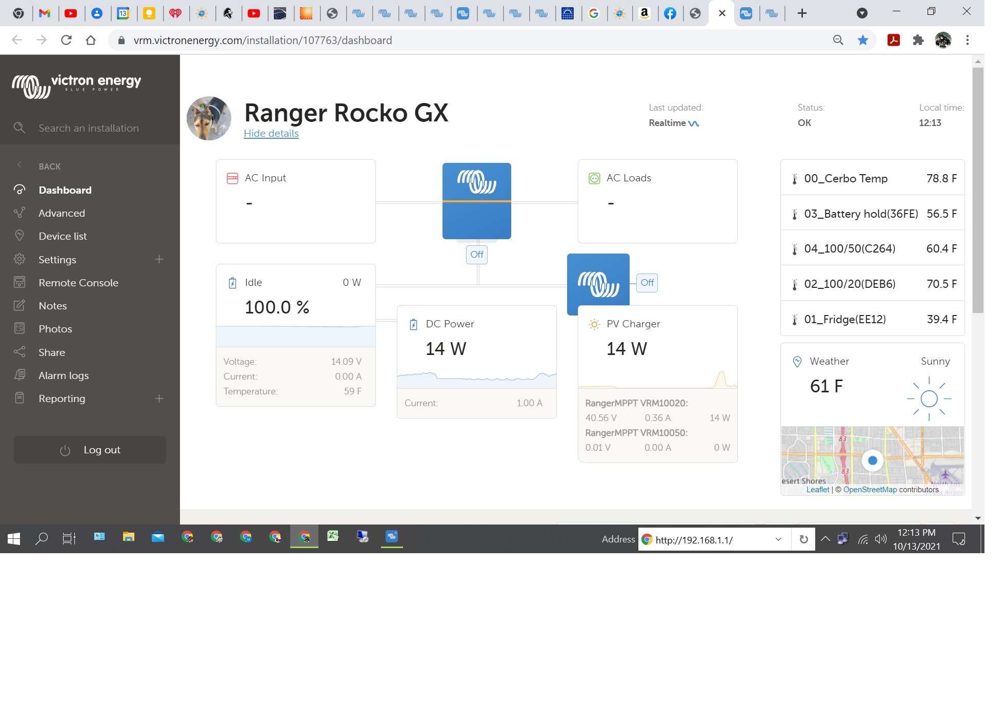
  1. In the VRM Dashboard display, the order of them is not configurable even if all inputs are named to be alphanumeric and/or alphabetical. In this photo, all analog inputs are named and list properly in the Remote console but not in the Dashboard. It appears that the Dashboard lists them solely on order of initial contact reading from the CerboGX.vrm-dashboard20211013.jpg
  2. A RuuviTag that is removed either by deselecting the "enable" tab or completely removing it from the Remote Console does not become deleted from the Remote Console as long as it is still within BT range of the CerboGX. The way that I was able to get the RuuviTag to not show up inside the Remove Console was to move it out of BT range AND then reboot the CerboGX. vrm-dashboard20211013a.jpg
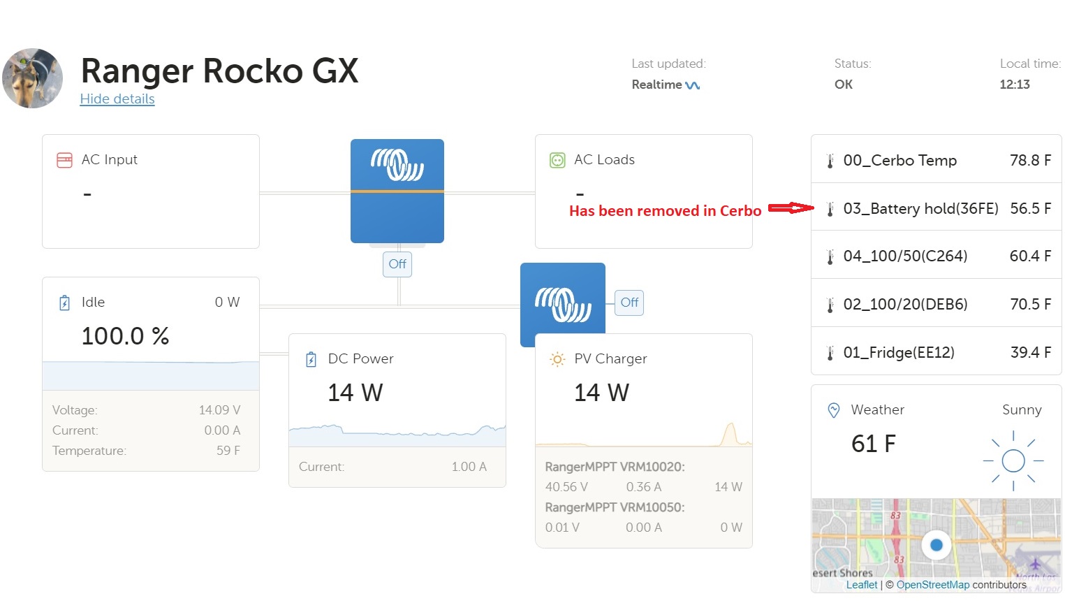
  3. A RuuviTag that is removed from the Remote Console does not become deleted from the Dashboard. Even taking the RuuviTag out of range of the CerboGX doesn't work. See photo above, item "03_Battery hold(36FE)". In the photo below, the RuuviTag "Ruuvi 36FE" has been removed from the Remote Console by deselecting it from this Bluetooth Sensor menu, then from the Remote Console device list "device remove" switch, and finally by rebooting the CerboGX. Without rebooting, it will remain in the Bluetooth device list.vrm-dashboard20211013b.jpg
  4. The RuuviTag(s) do not show up in the Device List within VRM controls. I believe that this is why any that are removed via the Remote Console can not be deleted in VRM. A physically attached temperature input to the CerboGX can be removed in VRM by this Device List.vrm-dashboard20211013c.jpg

3 comments
2 |3000

Up to 8 attachments (including images) can be used with a maximum of 190.8 MiB each and 286.6 MiB total.

kris avatar image kris commented ·

I have the same problem with removing Ruuvi from console, same is when I configured DC energy meter as solar charger and it got removed but still shows in VRM

0 Likes 0 ·
Steve Preston avatar image Steve Preston kris commented ·
I think that tomorrow I will reload 2.73 and see if the RuuviTags are cleared from the VRM. I'll reply here with my results.
0 Likes 0 ·
Steve Preston avatar image Steve Preston kris commented ·
20211016 - I can confirm that reverting to 2.73 does not remove the Ruuvi tags from the VRM Dashboard. It's a nuisance but I'm confident that in do time, Victron will work out these minor bugs.


When I reverted, I used a LAN connection directly to the CerboGX to install 2.73. The install took a long time > 10 minutes and appeared to be "hung up". Several attempts during this time to reconnect via remote connect showed that it was still installing. After it was finally available to reconnect, it was only able to connect via BT but that kept halting @ 40% then back to 1%. I unpaired and then was able to reconnect after entering my existing BT password. Once reconnected via BT, I had to reestablish the Wi-Fi connection even though it had my network listed in the available list. Another couple of bug issues that I'm confident will eventually be sorted out.


So, back to reinstalling 2.80~24 to reenable the RuuviTags, I've already gotten reliant on them for my camper and its component temp data, especially my refrigerator.

0 Likes 0 ·
Paul B avatar image
Paul B answered ·

Have just upgraded a site with a cerbo from 2.63 to 2.80~21, The Raymarine MFD was working on 2.63 but now that the 2.80~21 firmware is active on that site the Victron Icon just shows a white page.


Reason we have a few test sites out on 2.80~21 - Have upgraded a few for our sites for testing as I am testing the new 123smart software for interfacing to the GX devices with Sebastiaan's help, ( there new software only works on 2.80 and the newer Python)

2 |3000

Up to 8 attachments (including images) can be used with a maximum of 190.8 MiB each and 286.6 MiB total.

Dosheimer avatar image
Dosheimer answered ·

Hi!
I still do not understand what to expect from the new DC meter function: There is a 115A alternator, a Silentwind generator and MPPT100/50 (500Wp solar panels) in my system as charging sources for my 330Ah lithium (cruising sailboat setup).

All negatives of the charging sources are connected to a central minus distribution busbar and this minus busbar is connected to the shunt of aSmart BMV712 which then is connected to a 330Ah smart lithium from Victron.

So far I am getting fine readings on the VRM screen from the MPPT100/50 which is connected to the Raspi4 running Venus V2.80-16-large21, but no additional widgets for additional charging sources or something like that.

So when switching the BMV712 to DC meter mode: What shall happen when getting charging amps from the wind generator and/or alternator? Maybe I am completely misunderstanding the whole topic about the new DC meter feature?

1634933904703.png


1634933904703.png (72.6 KiB)
2 |3000

Up to 8 attachments (including images) can be used with a maximum of 190.8 MiB each and 286.6 MiB total.

Related Resources