question

mvader (Victron Energy) avatar image
mvader (Victron Energy) asked

Wiring Unlimited - a new book

Hi all,

Margreet Leeftink, Sales Manager & trainer in Australia has compiled the second Victron book: Wiring Unlimited.

I'm posting it here on Community as a preview; please put in your comments so we can make it even better before publishing more publicly.

Download your copy here.

I could of course here tease more with whats inside; but better just click the link and see for yourself. I think its a great step forward of bringing all information together as opposed to it being scattered around.


Thank you Margreet for this excellent piece of work! Wie schrijft die blijft :-).


Best regards,

Matthijs

wiring
8 comments
2 |3000

Up to 8 attachments (including images) can be used with a maximum of 190.8 MiB each and 286.6 MiB total.

murph avatar image murph commented ·

Looks great from a very brief first look.

I would add a little detail in the resistance section regarding loose or bad connections & contacts. The localised heating around a high resistance connection is based on P=I²R. With the high current in extra-low voltage DC, it takes very little resistance to generate a destructive level of heat. That could do with a bit more emphasis, in my opinion, as it's a major cause of damage to equipment and cabling (and fire in extreme cases).

2 Likes 2 ·

Hi Murph, That is a good suggestion, and I totally agree that local heating due to a bad connection can be quiet bad. I will add something on resistance of connections and the effects in the next version. Thank you.

0 Likes 0 ·
Michael Riley avatar image Michael Riley commented ·

Very good all round intro and guidance. Well done.

From a totally seperate perspective I believe there are a few pagination, grammatical and other (dutch-english) phrasing that could be tidied up for those of us who like the english language. Tried to 'comment' on the pdf version (using Markup) but it got time consuming and very clumsy after 20+ corrections/suggestions. Decades working for Dutch or German companies I can read 'through it' but thought we could do it right from the beginning if at all interested. If you want any assistance just send me an editable version and I will make my suggestions with 'corrections on' which you can make up your own mind on (accept/reject). I use natively a MacBook Pro which can read word or other.

@mvader (Victron Energy Staff)

1 Like 1 ·
Margreet Leeftink (Victron Energy Staff) avatar image Margreet Leeftink (Victron Energy Staff) ♦♦ Michael Riley commented ·

Hi Michael, It could most definitely do with tiding up. And it for sure contains "Dunglish" ;-). The idea was to release a very early draft version so we could post it in the community and listen to the remarks and implement them in the next versions. The English will also improve in the next versions. Once I have made the next draft version i would be happy to run it by you.


0 Likes 0 ·
John Rushworth avatar image John Rushworth ♦♦ commented ·

That is a superb document. Needs an ending/conclusion, maybe a glossary.


It’s the kind of booklet us old steam engineers could have done with 7 years ago! Although I did know the basics from Royal Navy college days, it’s great to have such a comprehensive Victron flavoured document. Amazing work by Margreet.

0 Likes 0 ·
energy-z avatar image energy-z commented ·

Nice :)

Thanks for sharing it with us :)

0 Likes 0 ·
Warwick Bruce Chapman avatar image Warwick Bruce Chapman commented ·

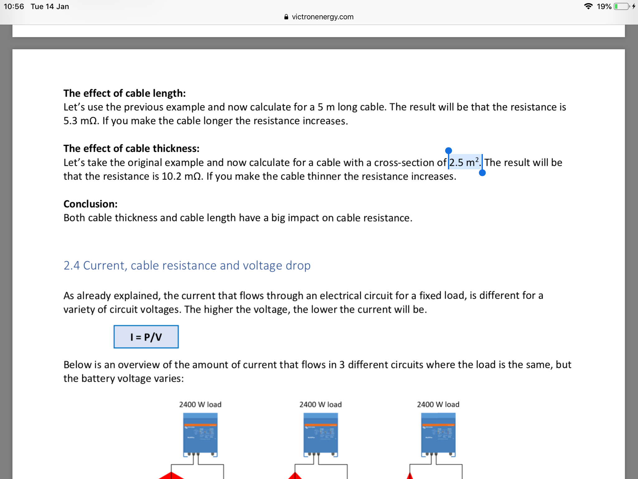
A correction m2 should be mm2:

alt text

0 Likes 0 ·
Margreet Leeftink (Victron Energy Staff) avatar image Margreet Leeftink (Victron Energy Staff) ♦♦ Warwick Bruce Chapman commented ·

Thanks for pointing this out. I will correct this in the next revision of the book.

0 Likes 0 ·
19 Answers
paulo3233 avatar image
paulo3233 answered ·

Hi,

Very good book. Full of information!

Thank you.

2 |3000

Up to 8 attachments (including images) can be used with a maximum of 190.8 MiB each and 286.6 MiB total.

markus avatar image
markus answered ·

This is super helpful.

Thank you very much!

2 |3000

Up to 8 attachments (including images) can be used with a maximum of 190.8 MiB each and 286.6 MiB total.

Bill avatar image
Bill answered ·

I would change the way the links in it work so they open a new page instead of opening the link in the current page. As when you use the back button you go back to the top of the book instead of where you were.

I use Google as a PDF reader. It may be different if adobe is loaded. Being an IT guy, less things installed on a computer the better it works...:) -Bill

1 comment
2 |3000

Up to 8 attachments (including images) can be used with a maximum of 190.8 MiB each and 286.6 MiB total.

Thanks, I will look into that. It probably has something to do with the PDF converter I used.


0 Likes 0 ·
Stefanie (Victron Energy Staff) avatar image
Stefanie (Victron Energy Staff) answered ·

Super helpful. Thank you!

2 |3000

Up to 8 attachments (including images) can be used with a maximum of 190.8 MiB each and 286.6 MiB total.

a-v avatar image
a-v answered ·

Great work, Margaret! Thank you, especially for the numbers and examples! Good to have everything in one doc. Lots of useful information and also tricks that I have not read elsewhere.

If I can wish I would like to have the concrete voltage values for the BatteryBalancer like in the ripple section so we do not have to go to the link for it.

Just a small thing: you can not connect 360W PV array to a 75/15 MPPT charger on 12V as it will be overloaded.

A third proposal: as most of the manuals are missing the right torque values, a torque table would be of much help.

Thanks again.

Viktoria

2 comments
2 |3000

Up to 8 attachments (including images) can be used with a maximum of 190.8 MiB each and 286.6 MiB total.

Hi Viktoria, Thank you for the suggestions.

I will change the Battery balancer voltages

I will look into adding torque settings. I might keep it general. For example M8 bolts xx Nm, M6 bolt xx Nm and so on. It will be added to next draft version.

I will check your remark about the 360W panel wit R&D. I was under the impression that it is possible and that the MPPT will current limit. Over current is allowed, but over voltage will damage the controller. I will get back to you on this.

0 Likes 0 ·
Margreet Leeftink (Victron Energy Staff) avatar image Margreet Leeftink (Victron Energy Staff) ♦♦ Margreet Leeftink (Victron Energy Staff) ♦♦ commented ·

Viktoria, I checked (just to be on teh safe side). It is possible to connect a 360W panel to a 15A MPPT

0 Likes 0 ·
JohnC avatar image
JohnC answered ·

Stunning stuff, thank you Margreet. And of all the things that caught my fancy, the treatment of the Victron logo on the opening page is a masterstroke of art. (Don't you ever edit that out Matthijs, it's a gem).

I encourage the use of links too, whether they be to Victron kit or even outside suppliers such as cable maufacturers. Doesn't need to be to a product even, just well-written info from anywhere, for those who wish to delve deeper into a topic.

And yeh, "writers are never forgotten". I hope Matthijs remembers at salary review time.. :)

Good work.


3 comments
2 |3000

Up to 8 attachments (including images) can be used with a maximum of 190.8 MiB each and 286.6 MiB total.

mvader (Victron Energy) avatar image mvader (Victron Energy) ♦♦ commented ·

> Don't you ever edit that out Matthijs, it's a gem

Are you a mind reader? :-)


0 Likes 0 ·
JohnC avatar image JohnC ♦ mvader (Victron Energy) ♦♦ commented ·

Ha, I've just had long (too long) experience with CEO's, and indeed was one myself.

If you must, trick it up with a Van Gogh background, but don't take it down for a bland company logo.

But all in fun, let's keep having it.. :)

0 Likes 0 ·
Margreet Leeftink (Victron Energy Staff) avatar image Margreet Leeftink (Victron Energy Staff) ♦♦ JohnC ♦ commented ·

I was wondering when Matthijs would comment on my modified logo :-)

I wil look into adding more links. Thanks for the remarks.

0 Likes 0 ·
dazey77 avatar image
dazey77 answered ·

Nice book. I am not really the target audience being electronic trained but its nicely done.

Good to see someone sharing my hatred of cigarette outlets (which are a complete bodge never having been designed for power) but I think its really missing an alternative. Personally I am using Lemo connectors for consumer 12v outlets, really nice fittings not really for mass market and I wouldn't recommend them to the general public. I am sure people could do with a good alternative but I am not sure what is best to use?!

Also missing within connectors section the general purpose multi connectors for 12v use to allow removal of appliances etc. To me you should alway be able to pull out the fridge/whatever and disconnect a connector behind to allow it to pull out (like the 2.8mm and 6.3mm spade connector range)

5 comments
2 |3000

Up to 8 attachments (including images) can be used with a maximum of 190.8 MiB each and 286.6 MiB total.

Thanks for the info. I will look into Lemo connectors. Always fun to try something new.

I do mention spade connectors. but there is minimal text, i might expand that a bit.

0 Likes 0 ·
boekel avatar image boekel ♦ commented ·

Can you advice a certain type of Lemo connector? they've got quite a range..

0 Likes 0 ·
dazey77 avatar image dazey77 boekel ♦ commented ·

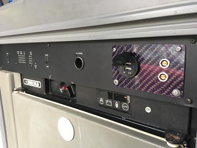
I use the 0B and 1B. The 0B I use for GPS, I have had inline connectors out in the rain on motorbikes for years. Excellent cable restraint and you just push the connectors together, they lock and you just pull to unlock and release. Never had one fail in 10 years in the elements (not officially a water proof range)

The 1B are rated up to 5A at 12V and I use them in the van for higher loads (laptops, Nuc PC etc). They have panel mount too. Same easy connection, locking and disconnection.

This is two 1B to the left of the USB charger. One can always go further up the push-pull range to get higher contact loads.

From memory the 0B is 2-3A rating.

1 Like 1 ·
img-0919.jpg (70.2 KiB)
Margreet Leeftink (Victron Energy Staff) avatar image Margreet Leeftink (Victron Energy Staff) ♦♦ boekel ♦ commented ·

I had a look at the Lemo conenctor range https://www.lemo.com/catalog/ROW/UK_English/connector_selection_guide_eng.pdf

They are indeed nice connectors, only not suitable for high currents. (unless i am missing something?)


0 Likes 0 ·
dazey77 avatar image dazey77 Margreet Leeftink (Victron Energy Staff) ♦♦ commented ·

No, your right. I like them and the current rating is enough for me but they are not intended as power connectors. I originally started using them as an alternative to 2.3mm multi connectors because I was connecting and removing all the time. They are also small for their current rating as they are well engineered.

Not sure what the larger ranges get to but 5A works for my consumer stuff, not going to suit everyone,

I still think the market needs a better solution than this (which was why I wasn't recommending them to the market, more provoking the conversation!)

0 Likes 0 ·
dazey77 avatar image
dazey77 answered ·

The ratings are actually a little higher than I remember but there are limits to what is sensible in the size in terms of termination (page 57). Suggests you can get 15A through the 1B, not sure I would dare but I suppose 15 failure is 10 operating.

https://www.lemo.com/catalog/ROW/UK_English/unipole_multipole.pdf

By the time you get to the 5B series your into some serious current ratings for the two pole connector (but the connector costs for a 5B are probably prohibitive)

2 |3000

Up to 8 attachments (including images) can be used with a maximum of 190.8 MiB each and 286.6 MiB total.

Pat Davitt avatar image
Pat Davitt answered ·

Margreet,

Just got around to reading the book, it's great. Not sure what Victron is paying you, but it's not enough. Sorry Matthijs. :-)

@Margreet Leeftink (Victron Energy Staff)

Second a prior post about including the importance for proper torquing of connections. It's a pet peeve of mine.

Pat

2 |3000

Up to 8 attachments (including images) can be used with a maximum of 190.8 MiB each and 286.6 MiB total.

kai avatar image
kai answered ·

Nice collection of engineering notes. A few comments -

1) Could emphasise danger of wearing jewellery (incl. ring!) or any metallic items when working on bare busbars. Uninsulated spanners are not the only cause of shorts.

2) Some battery isolator switches are not designed to break current (esp DC current).

3) Some words about best practice in shutting down and restarting DC systems may be helpful. E.g. sequencing shutoffs, and precharge before restarting etc. These practices improve contactor lifetimes and minimises the possibility of arcing which may trigger further undesired actions from being startled.

1 comment
2 |3000

Up to 8 attachments (including images) can be used with a maximum of 190.8 MiB each and 286.6 MiB total.

Hi Kai,

Nice remarks, I will look into adding this in next version.


0 Likes 0 ·
alan avatar image
alan answered ·

Excellent work on this, with the section on earthing, off grid, grid connected etc.

It would be good to have a note on what the ground relay tick box in ve config should be set to for the different system types.

1 comment
2 |3000

Up to 8 attachments (including images) can be used with a maximum of 190.8 MiB each and 286.6 MiB total.

Thanks for the sugegstion. I will add it to next version.

0 Likes 0 ·
mikeb avatar image
mikeb answered ·

Hi


A good read


Was interested in the ve bus connection and disconnection. Haven’t read in any of the manuals etc about the implications of disconnecting the negative supply when the ve bus coms cables are still connected to the ve bus and the possibility of damage


Regards

Mike

2 |3000

Up to 8 attachments (including images) can be used with a maximum of 190.8 MiB each and 286.6 MiB total.

robinjay avatar image
robinjay answered ·

Hello:

Check the formula on page 5.

2 |3000

Up to 8 attachments (including images) can be used with a maximum of 190.8 MiB each and 286.6 MiB total.

robinjay avatar image
robinjay answered ·

Hello:

Check the formula on page 5.

3 comments
2 |3000

Up to 8 attachments (including images) can be used with a maximum of 190.8 MiB each and 286.6 MiB total.

Do you mean the forrmula for the resistance of a length of cable?

Can you let me know what you think is the problem with this formula?


0 Likes 0 ·
robinjay avatar image robinjay commented ·

Hello:

Spelling of lenght

Here are some more things to look at:

Page 5: this why, short circuit

Page 13: their>its

Page 18: dimeter>diameter

Page 19: Raduis>Radius

Page 20: the are > they are , with> width

Page 21: unisulated > uninsulated

Page 22: ferules > ferrules , insolated > uninsulated, enter > entering

Page 30: curcuit > circuit , acidental > accidental , what is "un "?

Just some things after quick review. Would like to see something on US split-phase.

Would like to see electrical specs on comm cables VE.Direct USB and VE.Bus USB, and complete electrical on each wire (isolation especially).

R.

0 Likes 0 ·
Margreet Leeftink (Victron Energy Staff) avatar image Margreet Leeftink (Victron Energy Staff) ♦♦ robinjay commented ·

Thanks, I will correct in next version.

0 Likes 0 ·
abrahamsolar avatar image
abrahamsolar answered ·

Hello, @Margreet Leeftink (Victron Energy Staff) & all. Please review the "rule of thumb" for AC wire gauge calculation at bottom of the document page 33. That seems to be calculating a gauge too small from the ampacity standpoint.

Margreet's book might do well to explain "nominal current" should be the pass through amps if the inverting amps is smaller. Emphasizing that the rules of thumb are based on copper conductors (instead of aluminium) also might help first time Victron users.

My math below is based on the National Electrical Code commonly used here in the US. Acknowledged that wire gauge practices for a boat or caravan--or a solar home outside the US--may be different & governed by ABYC or other standards.

If pass-thru is 100 amps AC, dividing by 8 = 12.5 mm2 cross section which seems about two wire sizes too small for ampacity. Dividing by 4 seems better which would yield 25 mm2 wire cross section in this example. (For American readers, 25 mm2 is comparable to #4 AWG.) Voltage drop should also be calculated & the biggest wire gauge result trumps the smaller one.

Margreet mentions the Victron toolkit phone app--but the Wiring Unlimited document might do well to emphasize that the phone app only calculates for percentage voltage drop & doesn't calculate for ampacity.

I remember the original Energy Unlimited book from Reinout & company in the early 2000's & Margreet's new book is a worthy successor.

Definitely we need torque values for the AC & DC connections & even for small things like temp sensors or relay terminals. The various installation books need this info, as well,or maybe that should go into the Victron Toolkit @mvader (Victron Energy Staff).

Thanks & Jolliness


3 comments
2 |3000

Up to 8 attachments (including images) can be used with a maximum of 190.8 MiB each and 286.6 MiB total.

abrahamsolar avatar image abrahamsolar commented ·

@Margreet Leeftink (Victron Energy Staff) you don't mean for your rule of thumb to calculate the cable diameter in mm instead of the cross section in mm2...do you? If so, the rule of thumb seems way off in the other direction. Tks

0 Likes 0 ·
boekel avatar image boekel ♦ abrahamsolar commented ·

it does say:
Nominal current / 8 = core diameter in mm

so yes, diameter.

so let's take 16A /8 = 2mm --> (2mm/2)^2*pi = 3,14mm2 = a little big indeed

32A / 8 = 4mm diameter --> 12,5mm2 = way to big

indeed, not a good rule of thumb (I don't know a good one, just look at the tables myself)

Also: page numbers would be nice to find the pages faster.

0 Likes 0 ·

Hi,


The rule of thumb is something one of my older colleagues used a lot. i will have a good look at it. Thanks for pointing it out.


0 Likes 0 ·
Stephen Otto avatar image
Stephen Otto answered ·

I had been searching around for something like this book for quite some time. Finally found it. Thank you....game-changer!!

2 |3000

Up to 8 attachments (including images) can be used with a maximum of 190.8 MiB each and 286.6 MiB total.

glenn-matthiesen avatar image
glenn-matthiesen answered ·

Hi Margreet,

Thank you for this excellent resource. An essential reference for anyone planning a renewable energy system.

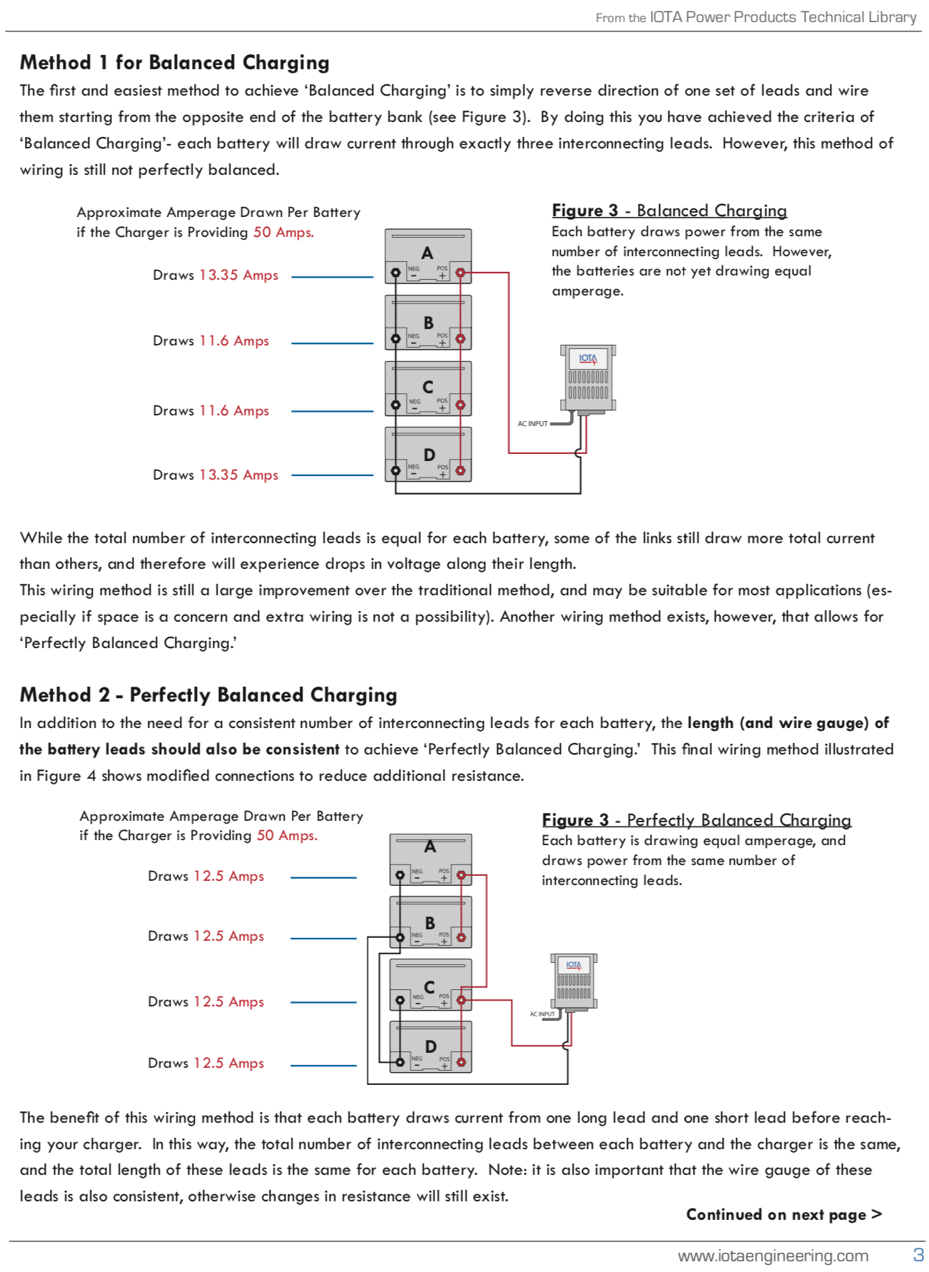
I noticed in Section 3.3 Parallel Battery Wiring, page 19, the diagrams of "correct" parallel wiring, appear not to be the best option.

IOTA Engineering published an article on the subject of balanced charging. https://www.iotaengineering.com/pplib/balancedcharging.pdf

Here is an excerpt;

Also of note, with regard to the installation of an RCD(s) within a system. No mention is made of the NEC Code requirement that an RCD must be installed between a PV array and the MPPT.

This information should be included within 4.10 Solar panels and page 56, Where to mount a RCD.

Also, on page 61, the statement;

Isolation of MPPT solar chargers

No isolation between PV input and DC output

Basic isolation between input/output and chassis.

This statement is rather brief and unclear to me. Can you elaborate?

Best regards,

Glenn


1 comment
2 |3000

Up to 8 attachments (including images) can be used with a maximum of 190.8 MiB each and 286.6 MiB total.

Hi Glenn,


Thanks for letting me know. I just have added it to next revision.

0 Likes 0 ·
brinx38 avatar image
brinx38 answered ·

This was an excellent read.

Thank you very much.

As a suggestion for completeness on the topic, I would add a section that speaks to why a Precharge Circuit might be needed when using large inverters with low resistance batteries (ie. Lithium).

Something like the info contained in this link

Thanks again for putting this together.

1 comment
2 |3000

Up to 8 attachments (including images) can be used with a maximum of 190.8 MiB each and 286.6 MiB total.

Thank you for pointing this out. This is actually also the case when you connect a large lead acid bank to an inverter. This is why you see a spark when connecting an inverter. Normally this only occurs once, during the initial install. The nature of a system that contains an inverter/charger is that these usually do not get disconnected from the DC supply.

But it is a slightly different story with a lithium battery. The lithium battery contains a BMS and the BMS will disconnect the battery when it is almost empty. Of course, this is also something that needs to be avoided, and this should not occur very often. But when a BMS has disconnected from the battery, it will not reconnect until the DC bus is powered again. The DC bus will get powered as soon as AC is connected to the inverter/charger. It will start charging and power the DC bus. at the same time it has also charged its internal capacitors and the inrush current will not take place when the lithium BMS reconnects the lithium battery.

So instead of adding a pre-charge circuit in the installation, a very easy fix is to first connect the inverter/charger to and AC supply, wait until it starts charging and then connect the battery terminals.

I wil give this a thought and perhaps add this information to the next edition.

0 Likes 0 ·
abrahamsolar avatar image
abrahamsolar answered ·

Hello, @Margreet Leeftink (Victron Energy Staff) & all. I'm a Victron distributor in the USA & here are suggestions:

(1) Page 54 of version 05 Wiring Unlimited (discussing AC wiring) underscores the importance of following the product manual for "recommended cable lengths & thicknesses". However, the manuals for Quattro & Multiplus contain no chart for AC cables; something as simple as the chart for DC cables would improve the manuals.


(1a) The phone app Victron Toolkit addresses only voltage drop considerations for wire gauge decisions, but does not address ampacity considerations. Margreet, since the Toolkit app does calculate AC voltage drop for us, is there a target range of recommended AC voltage drop that would help people size their AC cables just right?


(2) Example: I've fitted a Quattro three phase trio with a 100 amp AC input breaker & a manual bypass switch, and the 50 hz Victron system is 230 volts from each phase to neutral, and it's 5 meters (one way) from the AC bypass switch to each Quattro--& the AC cabling would all be equivalent length/same cross section. The Toolkit app says we'll have only .3% voltage drop in that scenario with 25mm2 copper cables (7/10ths of a volt). Does this seem too fat, too skinny, or just right? The cable I'm considering has an insulation rating of 90 degrees C & I need to buy it soon. I'll probably use a second 100 amp breaker on the AC output & the same cable gauge, FYI.

(For community members in the USA, 25mm2 cross section is the same as American Wire Gauge #4.)


(3) Page 56 of the WU book discusses "chassis earth" connections, but has no guidelines on proper gauge for those connections relative to a particular inverter model. The manuals for Quattro & Multiplus are also silent on this topic so this is another opportunity for improved documentation.

(For community members in the USA, "chassis earth" is analogous to how we "bond" all the metal enclosures & frames together as part of the grounding system.) I'm considering #8 AWG copper for the earth connections in the above described Quattro setup--same as 10mm2 cross section--OK?


(4) Could Margreet's book be added to the Victron Dropbox? This way the latest version would always be the one that Dropbox participants would be referencing.


Thanks as always, community folks. Keep the sun shining.


3 comments
2 |3000

Up to 8 attachments (including images) can be used with a maximum of 190.8 MiB each and 286.6 MiB total.

Hi, thank you for your input. all very good points.

1) Wiring thickness for AC is less critical because the voltage is higher. Best to use the thickness recommended by your local house wiring standards.

1a) I would personally go for a voltage drop of less than 1.5%. But again, it is best to follow the local wiring standards. The wiring book was originally written for DC. Partly because DC has low voltages and low voltage does not usually have to meet meet official wiring regulations and can be done by unlicensed (and usually untrained) people. But AC wiring has to be done by licensed electricians and they have to follow the local wiring standards.

2) from the manual: The AC-in-1 input must be protected by a fuse or magnetic circuit breaker rated at 100A or less, and cable cross-section must be sized accordingly.

This means that the wire will need to be rated to the fuse value, so follow the local AC wiring guidelines to pick the correct cable thickness.

3) Earth (or ground) cables have to be thick enough to carry the potential current should a fault occur in the system. The cable thickness related to what loads are connected in the system. This can mean that this cable needs to be quite thick. Again, follow the local wiring regulation for this.

4) The book is located in the "products" Dropbox. look in the wiringunlimited folder.


I might add some of above text in a future version of the book.


0 Likes 0 ·
petajoule avatar image petajoule Margreet Leeftink (Victron Energy Staff) ♦♦ commented ·

Had a 2h-look at the book(let) and it's a quite nice hands-on summary. I especially like how it handles all the main wiring aspects that need to be taken care of in e.g. off-grid systems DC part (battery and PV), AC part.

It's perfectly ok if it is Victron centered and shows examples of Victron products and where to use them in the given application.

What I am missing though is the lack of such examples when there are no such products from Victron, or when the components are more off-shelf.

In my concrete case I am looking for a suitable - yet cost-effective - AC bypass switch (see 6.6) for my system. Unfortunately that 6.6 section adds exactly 0 value to my search for this component, as it merely describes requirements in general terms and is precisely missing what makes this book valuable in all the other places: examples.


0 Likes 0 ·
Margreet Leeftink (Victron Energy Staff) avatar image Margreet Leeftink (Victron Energy Staff) ♦♦ petajoule commented ·

I will look into this for a future update of the book.


0 Likes 0 ·