article

markus avatar image
markus posted

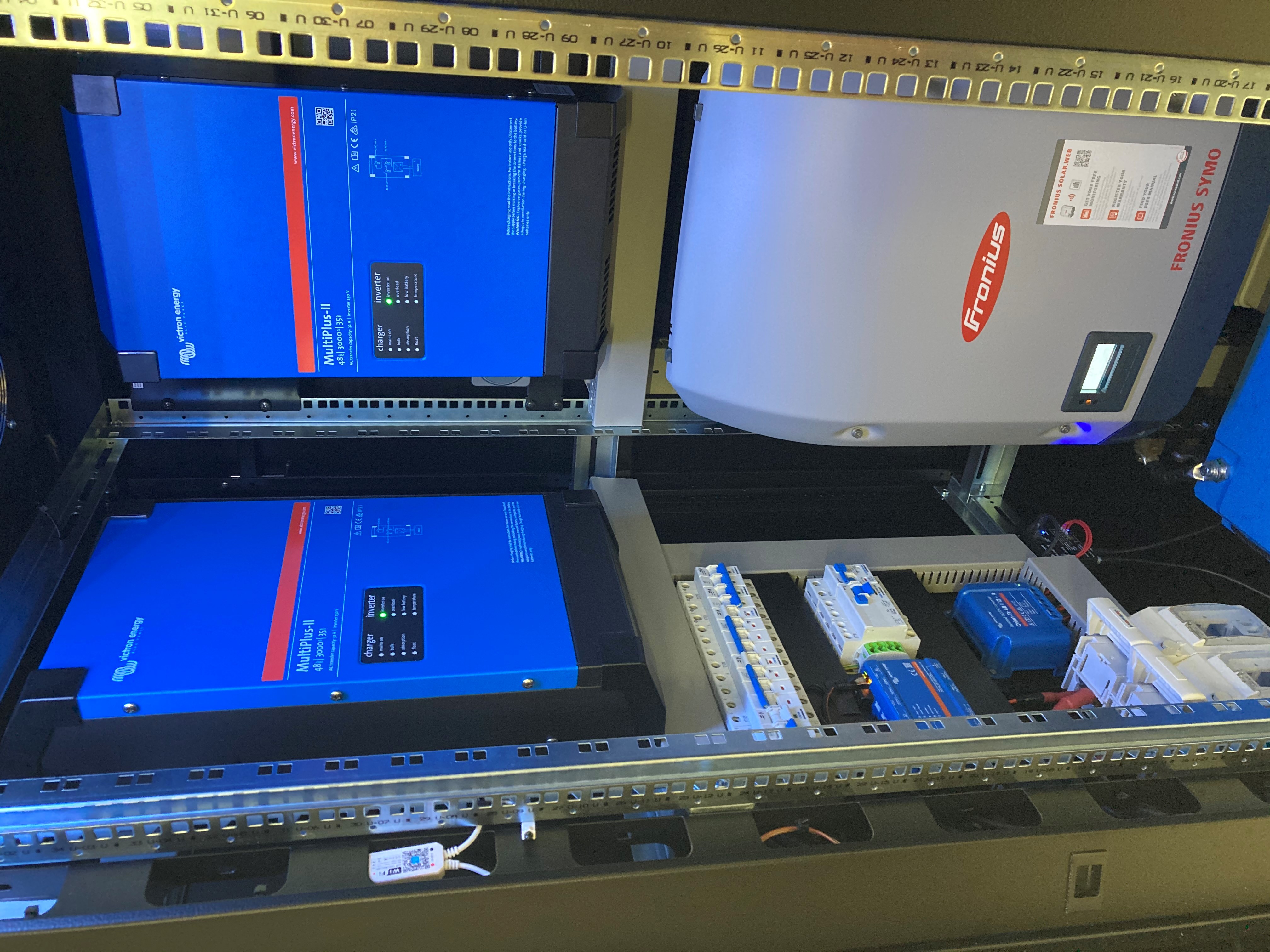
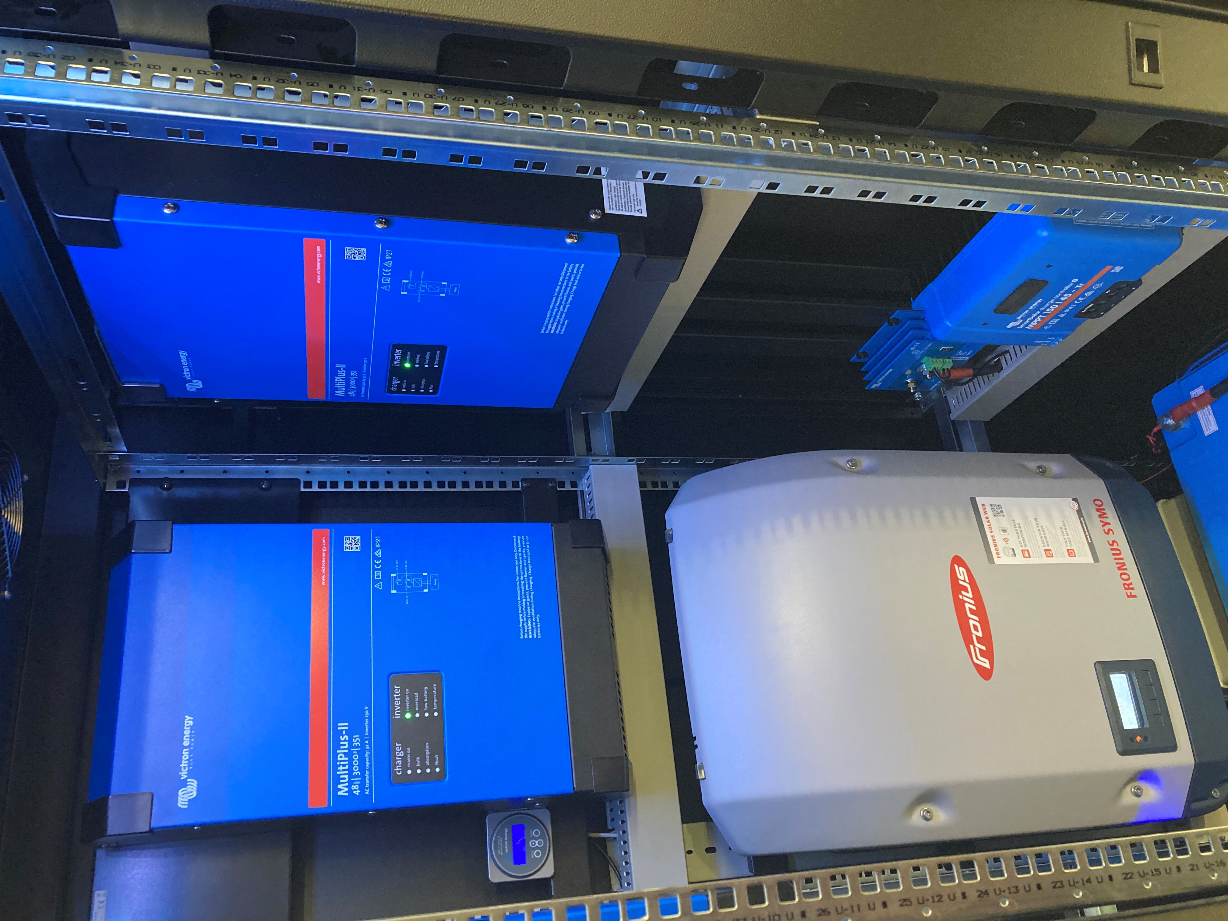
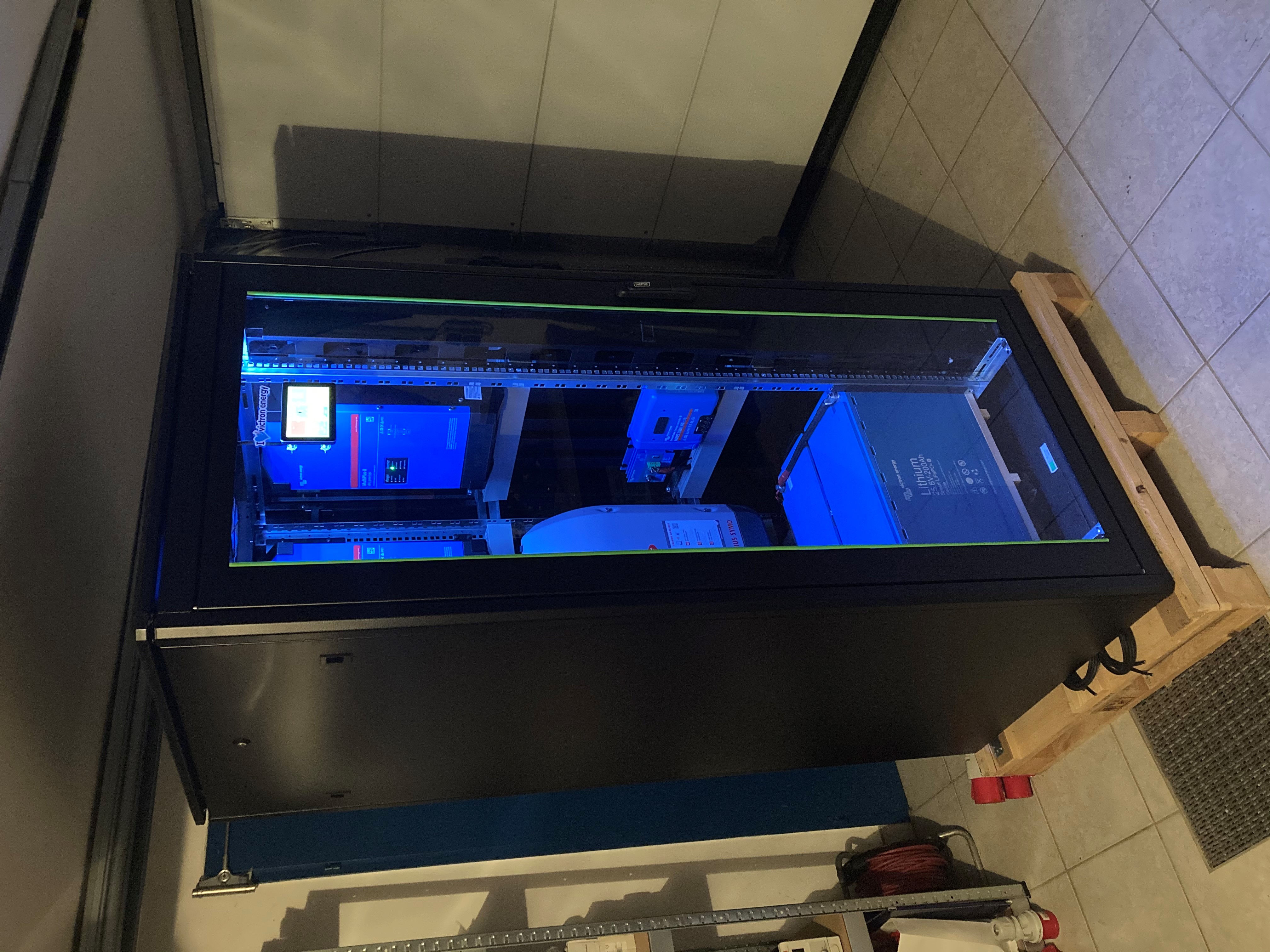
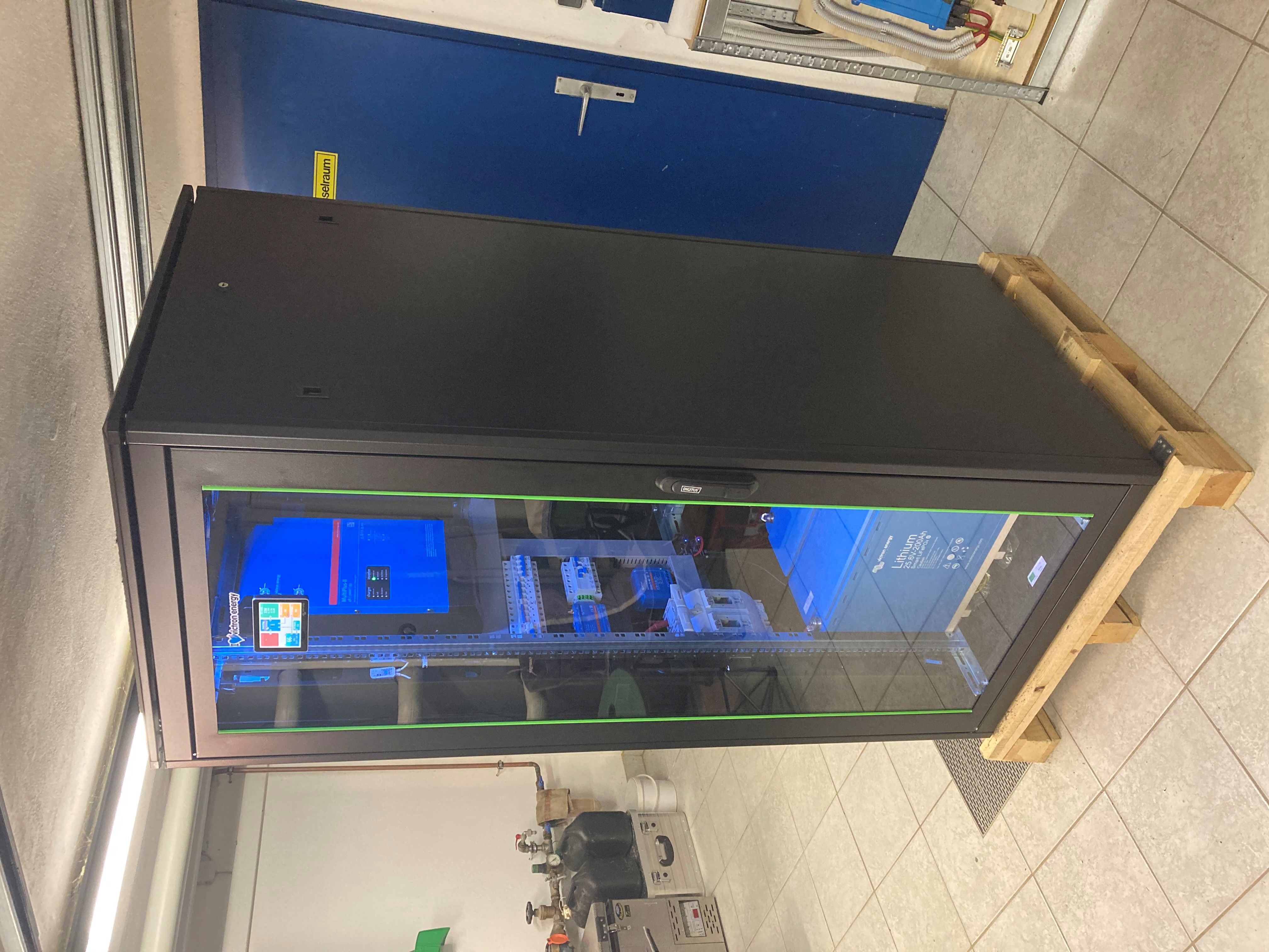
All in One 3-phase ESS system cabinet

Hello Community,

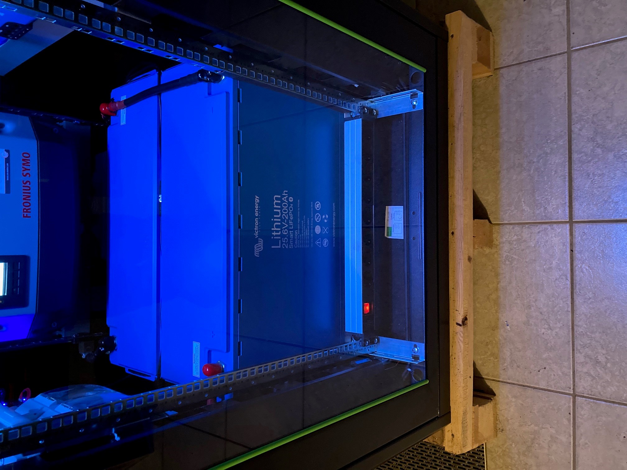
How compact can a 9000VA 3-phase ESS system, including 10kW/h batteries be?

I tried to find this out :o)
rack1.jpg

rack8.jpg

rack4.jpgrack3.jpg

5.1kWP of solar (15pcs. 340WP mono) panels will feed the Fronius (3kWP,9s,1p) and the Smart Solar MPPT (2kWP, 3s,2p)
rack6.jpgrack5.jpg

Four big 230V AC powered fans are mounted on the top, to do ventilation and to get the heat out, they are not even very noisy.

rack2.jpg

I am still waiting for the battery pole covers and a 19-inch rackmount 8-way Schuko distributor socket, to arrive. The distributor should cover the wooden plate underneath the batteries

rack7.jpg

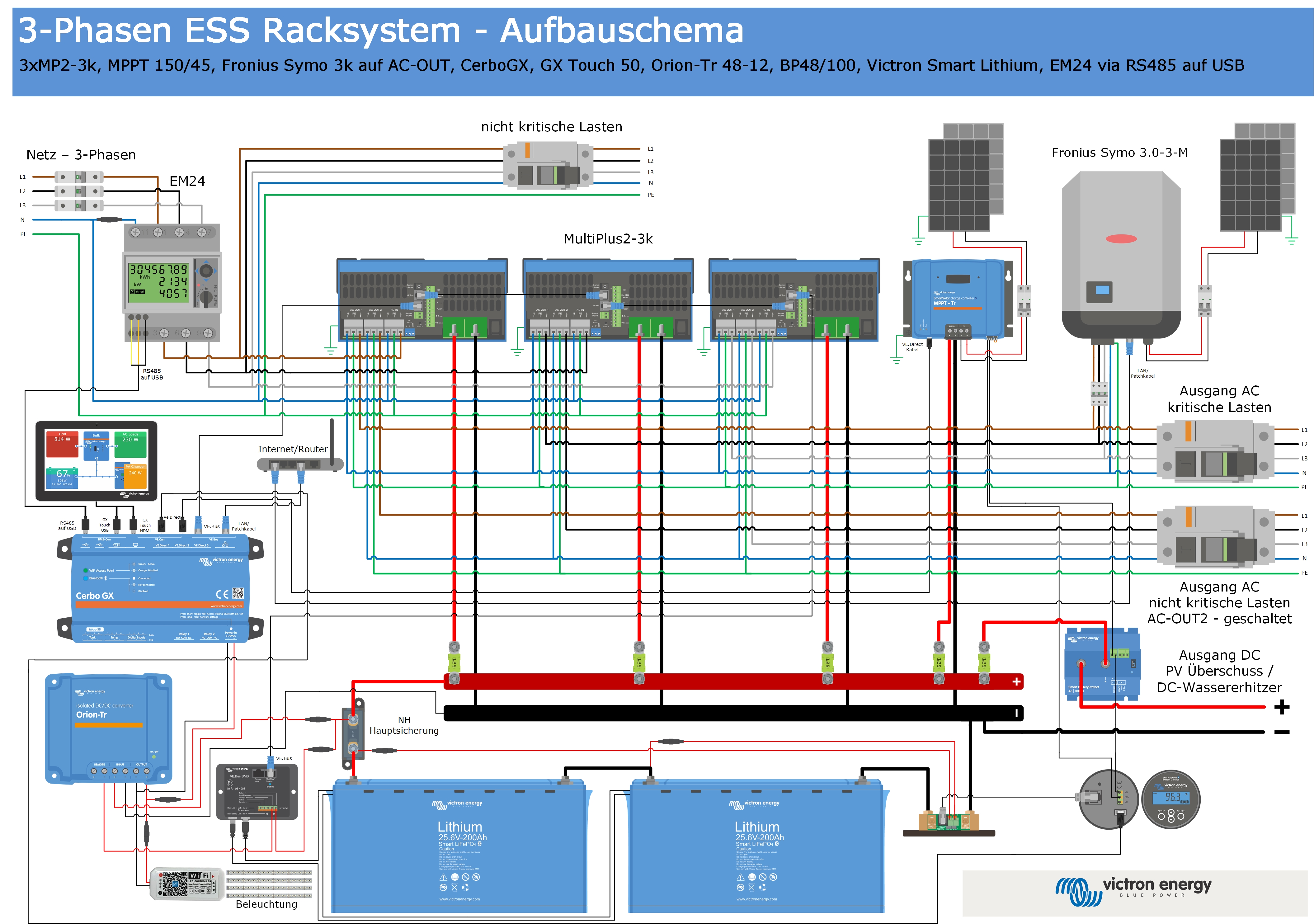
Excess PV power can be used, to heat water by 48V DC water heating elements. The 48V-100A Battery Protect is there, to switch the water heating elements on and off, so no danger of melting relay contacts exists. The BP is controlled by the BMV relay and the Smart Solar MPPT relay. I have no best practice ready yet in winter. However, first tests proof, that I have a good solution.


Schematic:
ess-cabinet.jpg

Partlist:


Stk. Description SKU

3 Stk. MultiPlus-II 48/3000/35-32 PMP482305010

1 Stk. SmartSolar MPPT 150/45-Tr SCC115045210

1 Stk. Cerbo GX BPP900450100

1 Stk. GX Touch 50 BPP900455050

1 Stk. Energy meter EM24 - 3 phase –

max. 64A/phase REL200100000

1 Stk. RS485 to USB interface cable 5m ASS030572050

2 Stk. VE.Direct Cable 3m ASS030530230

2 Stk. LiFePO4 Battery

25,6V/200Ah smart BAT524120410

1 Stk. M8 Circular Cable Male to Female

3 pole 1 m (Pack of 2) ASS030560100

1 Stk. VE.Bus BMS BMS300200000

1 Stk. Orion-Tr 48/12-9A (110W) ORI481210110

1 Stk. Smart BatteryProtect 48V-100A BPR110048000

1 Stk. Battery Monitor BMV-712 Smart BAM030712000

2 Stk. RJ45 UTP Cable 3m (VE.Bus) ASS030064980

2 Stk. RJ45 UTP Cable 0,9m (VE.Bus) ASS030064920

1 Stk. Fuse holder for MEGA-fuse CIP000100001

2 Stk. Busbar to connect 6 (1500 A) CIP100400070

5 Stk. Modular fuse holder for Mega-fuse CIP100200100

5 Stk. MEGA-fuse 125A CIP137125010

1 Stk. MEGA-fuse 500A CIP136500010


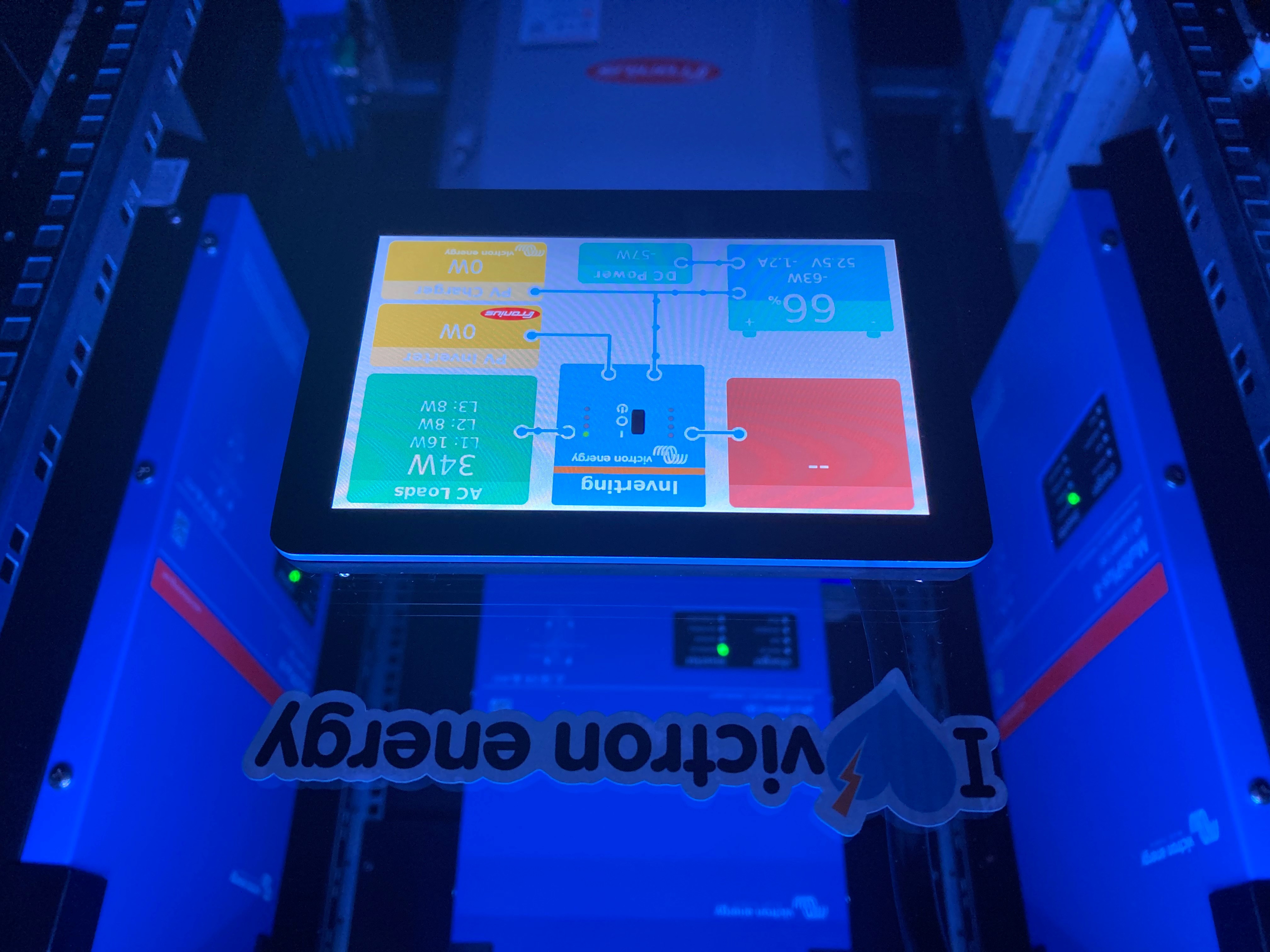
RGB LED strips on the top, light the cabinet’s internals.

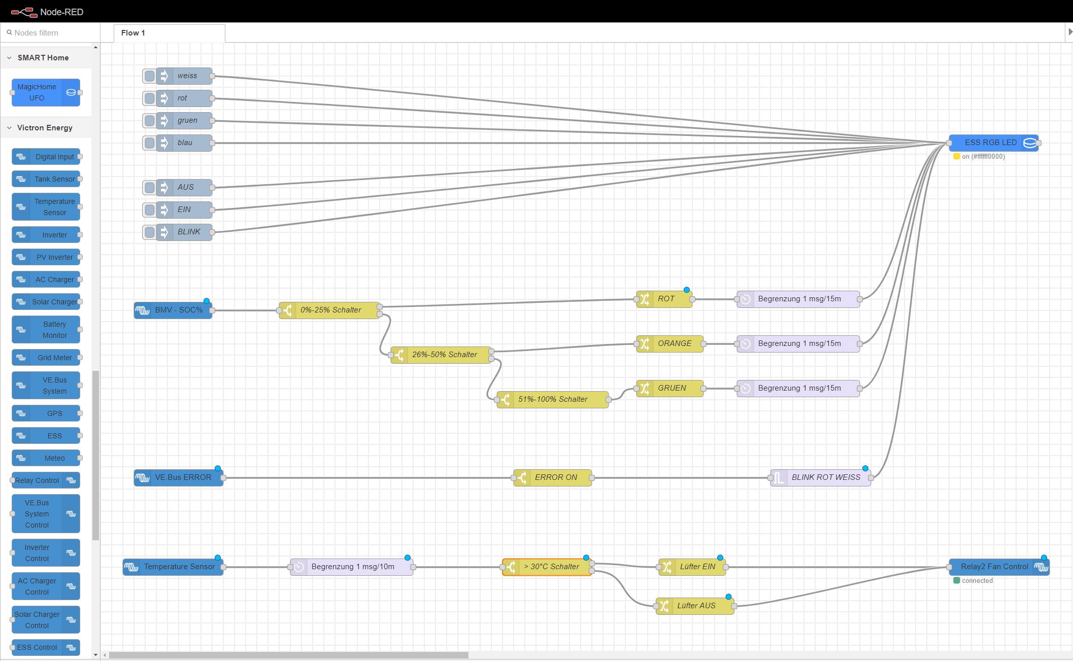
A Wi-Fi capable RGB LED controller powers the strips. It is possible to change colors on SOC, active warnings and alarms, etc. via Node-RED.

To make this happen, install the node-red-contrib-magichome node.

Information, how to get Node-RED running on a GX device can be found here: Venus OS Large image: Signal K and Node-RED [Victron Energy]

This is how the LED’s are controlled in Node-RED:
nodered.jpg


I want to create a more practical control logic for the excess PV water heater too, but for that I need better sunshine to do tests.

If there are questions about details, I am happy to answer them.


Best Regards,

Markus

Multiplus-IIESSMPPT SmartSolarLithium BatteryFronius
rack1.jpg (1.4 MiB)
rack8.jpg (2.4 MiB)
rack6.jpg (2.3 MiB)
rack5.jpg (2.2 MiB)
rack4.jpg (2.0 MiB)
rack3.jpg (2.0 MiB)
rack2.jpg (2.7 MiB)
rack8.jpg (2.4 MiB)
rack7.jpg (2.2 MiB)
ess-cabinet.jpg (2.6 MiB)
nodered.jpg (355.5 KiB)
rgb-led-video.mp4 (7.0 MiB)
11 comments
2 |3000

Up to 8 attachments (including images) can be used with a maximum of 190.8 MiB each and 286.6 MiB total.

wkirby avatar image wkirby ♦♦ commented ·

Outstanding Markus, that really looks good.
Thank you for sharing.

0 Likes 0 ·
Matthias Lange - DE avatar image Matthias Lange - DE ♦ commented ·

Wow! That's a very nice and clean installation!

0 Likes 0 ·
Show more comments
marekp avatar image marekp commented ·

@Markus

Can you explain why you placed the 3 MP-II inverters above the Fronius?

If they were below Fronius than they would be closer to the battery and the DC wires would be shorter

0 Likes 0 ·
Show more comments
markus avatar image markus ♦♦ commented ·

The missing parts arrived: distributor socket and pole covers.

distcover.jpg

0 Likes 0 ·
distcover.jpg (555.3 KiB)
thomasw-1 avatar image thomasw-1 commented ·

Hi Markus,

indeed, a very nice setup! I have not thought about such approach ;-( I simply assembled the components to a concrete wall.

Interestingly I have a quite similar setup (Fronius on AC-out and MPPT on DC side), where I also plan to use excess power for power to heat (in combination with a myPV device).

Especially with the Fronius on AC-OUT1 however I realized that in a zero-feed-in configuration, it gets throttled in such way that power is not transferred to the DC-level (in my case to load batteries).
In your case you might not have the Fronius excess power available neither for PTH nor for loading your batteries.


Therefore I would be highly interested, if you experience also these issues that I have in my setup:

Thanks
Thomas

0 Likes 0 ·
Show more comments
bslbatt-battery avatar image bslbatt-battery commented ·

10kwh-powerwall-battery-48v.jpg

From the pictures shared by our dealers, BSLBATT Powerwall battery and Victron, very beautiful layout design!

0 Likes 0 ·
jeancheyns avatar image jeancheyns commented ·


Hi Markus,

Very nice setup! I like it a lot. Which cabinet are you using?

0 Likes 0 ·
frankenstein avatar image frankenstein commented ·

Hello markus,

I love your rack-cabinet setup and will try to reproduce it.

Therefore I would like to ask you, how you have managed to mount the two MultiPlus on left and right side in the cabinet?

Greetings from Hessen ;-)
Frank

0 Likes 0 ·

Article

Contributors

Markus contributed to this article