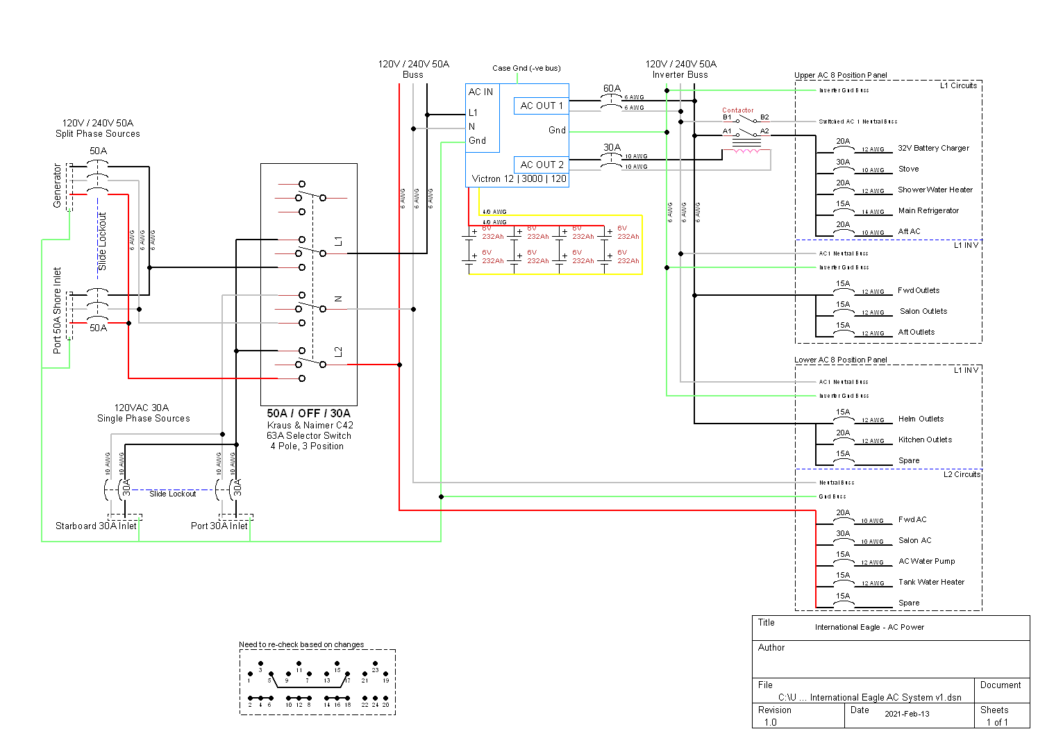
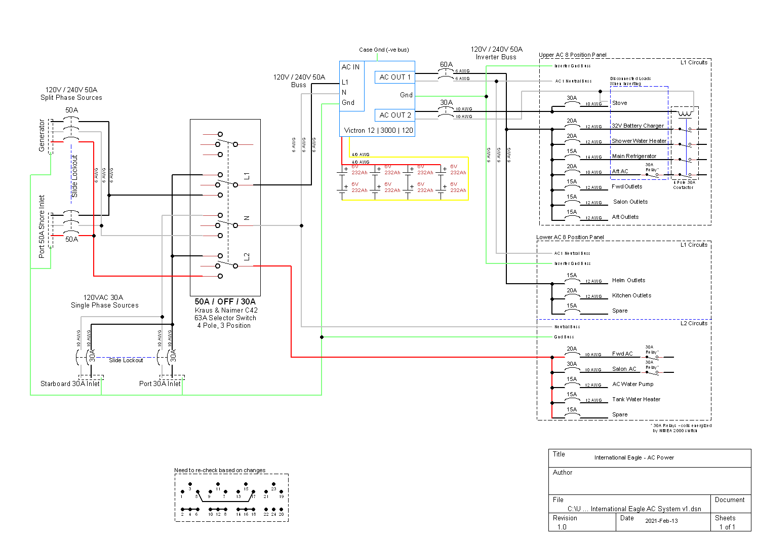
I've got a few Victron items on order (for a boat) and one of them is a Multiplus 12 | 3000 | 120. I'm installing this as part of an AC refresh, which will include moving from twin 120V 30A single phase inlets to a 120/240V 50A split phase. We have some favourite marinas that only provide a single 120V 30A dock outlet, which is why I've incorporated that into the design. This is AC only and doesn't show solar, Cerbo GX or the shunt, etc.
This is my first revision with the Victron in place, if you have a few minutes, please provide constructive criticism. Note, the contactor is there to provide higher capacity for switched loads running through the inverter and still allow all the features that the inverter provides to operate, such as power assist.
One of my questions is around circuit grounding for devices on the output side of the inverter (AC1 and AC2). As I've drawn it, there will be 2 ground busses - one before the inverter and one after. This is consistent with the schematics I've seen on the Victron site. I have seen other places where there is only one ground buss for everything - devices before and after the inverter share the same buss. Which is correct?
Thank you in advance for taking the time to assist!


