question

cz0911 avatar image
cz0911 asked

SEPLOS 48V 100AH Energy Storage Battery Compatibility?

I saw this video on YouTube. And thought their design not bad and Price acceptable. So I get connected with this supplier located in China. Called SEPLOS. It's a third-party manufacturing brand that not listed on Victron website.

Anyway, They told me that their packs could communicate with the Victron inverter. And they send me this picture of their pack and Victron inverter. Currently, I've got the Victron Quattro 48v 5000VA. And I'd like to have a try with their PUSUNG, which is a 48v 100ah pack.

126613889-396279451786280-1318025837473721659-n.jpg

Did anyone get a battery from this company before? I would like to know your review before formal purchase.

EasySolar All-in-Oneseplos
6 comments
2 |3000

Up to 8 attachments (including images) can be used with a maximum of 190.8 MiB each and 286.6 MiB total.

puitl avatar image puitl commented ·

Is it possible to see the voltage of every single cell in the VRM/Control-Panel?

Second question:

Does the DVCC-Function on my Victron system works with the Seplos?
(DVCC = set current- and voltage-reduction in the Victron system)

2 Likes 2 ·
p-fischer avatar image p-fischer commented ·

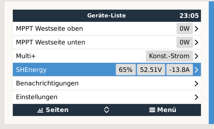
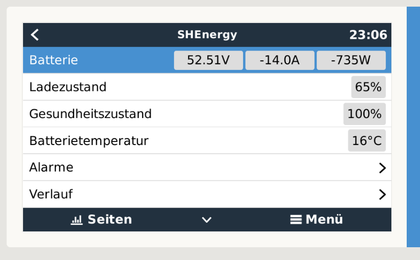
Hello, I have installed the Seplos BMS on my project for a short time. In my opinion, these are the same ones that are built into the battery packs from Seplos. I have 5 BMS running in parallel and one as a master which is connected to the CerboGX with Can. The pack addressing is done with DIP switches. And the parameters can be adjusted as required using PC software. Communication with the Cerbo works well, the BMS sends SOC, SOH, temperature, charging current, discharging current and charging voltage to it.


20211010-162402.jpg20211010-162410.jpg


unbenannt.pngunbenannt1.pngunbenannt2.png


unbenannt5.png

1 Like 1 ·
unbenannt.png (50.2 KiB)
unbenannt1.png (45.0 KiB)
unbenannt2.png (42.2 KiB)
unbenannt5.png (166.4 KiB)
ds1707 avatar image ds1707 p-fischer commented ·
Looks awesome, i have a multiplus 2 5000 and also a seplos BMS.

In your screenshot the SHEnergy is the Seplos right?
How did you configure the devices?

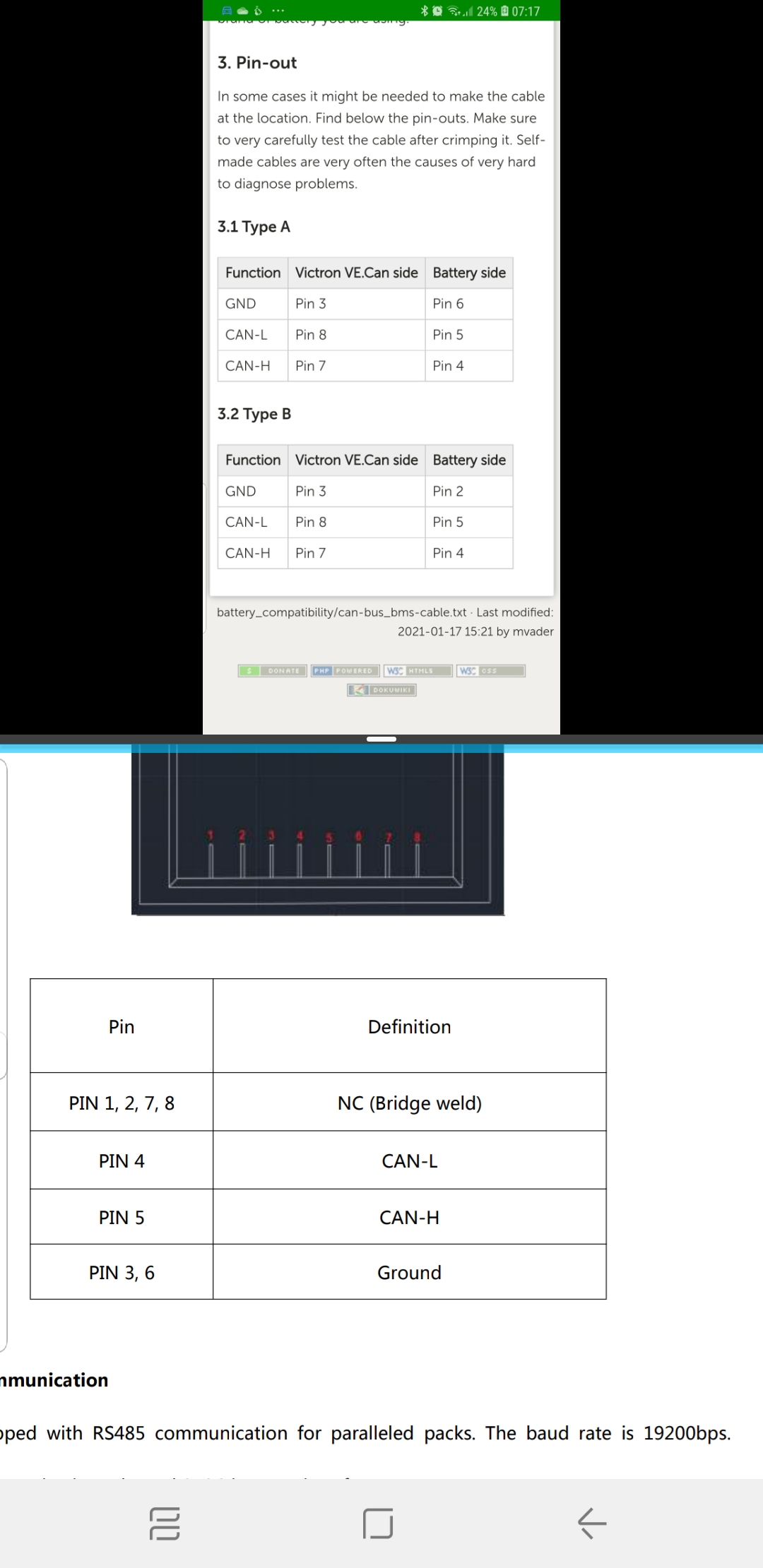
I cannot see my Seplos in the Venus.I use the Type A cable to connect BMS CAN and VE Direct.

Hope you can help me, maybe german would be ok for me. But english would be better so more people can follow.

0 Likes 0 ·
danielmar90 avatar image danielmar90 p-fischer commented ·
What type of cable have you used to communicate with victron ??
0 Likes 0 ·
Matthias Lange - DE avatar image Matthias Lange - DE ♦ commented ·

I'm sure you will need a GX device. The battery will not communicate directly with your Quattro.
On that picture they use a MultiPlus-II GX.

0 Likes 0 ·
cz0911 avatar image cz0911 Matthias Lange - DE ♦ commented ·

I've asked the supplier for the protocol they use. And I think they're compatible.

0 Likes 0 ·
14 Answers
Justin Cook avatar image
Justin Cook answered ·

Hi @Cz0911, welcome to the Community!

I've never heard of this company before now, but I'll note an important thing: Many companies claim that they are compatible with Victron equipment (and they're not always lying), but until Victron certifies that as well, then it's not Victron-supported and so you'll be on your own with it in terms of setup, programming, and any aberrant behavior that your system may exhibit in future.

While connection of Victron equipment in non-supported systems is certainly possible and often successful, the loss of your support options in case of unexpected behavior down the road is a very important consideration to take into account prior to making any purchases. And while connection in a non-supported system will not necessarily void your Victron warranties, it also might, depending on a vast array of factors, since connection to a non-supported battery is, by definition, a type of installation error... and any damage caused by installation error is not warrantable.

Basically: I advise that you tread carefully, research thoroughly, and take the loss of support and surety of behavior into account before making any purchases!

2 |3000

Up to 8 attachments (including images) can be used with a maximum of 190.8 MiB each and 286.6 MiB total.

Paul B avatar image
Paul B answered ·

They seem to have a CAN bus output from the picture, there are so many companies there in china, if you buy and it does not work correctly then its your risk, you get what you pay for usually, many a time I have learnt the hard way, you buy cheap then expect to have issues and you then have to be able to fix the issues.. The only way to know is to test it yourself and then you own it and have to deal with any issues, I agree with everything Justin has said.

dont do it buy one that is certified


if you do buy one MAKE sure it has a relay output for low signal and high signal. then if the can does not work you can connect to the 2 signal BMS assistant in the Multiplus II make sure you have access to there BMS settings and you can fine tune if need be.


1 comment
2 |3000

Up to 8 attachments (including images) can be used with a maximum of 190.8 MiB each and 286.6 MiB total.

peterwolff avatar image peterwolff commented ·

This picture is taken in my workshop and the battery is running fine since october 2020 in a ESS system. APsystems ac coupled with a multiplus 3000 gx. The battery BMS is programmed for Victron. We assembly in Spain these batteries and load bms with the correct software to run with CAN protocol. They are not (yet) on the list of compatible battery for Victron. They do not show any incompatibily with GX systems. Regards Peter Wolff- Clean Energy Solutions - Spain

0 Likes 0 ·
peterwolff avatar image
peterwolff answered ·

This picture is taken in my workshop and the battery is running fine since october 2020 in a ESS system. APsystems ac coupled with a multiplus 3000 gx. The battery BMS is programmed for Victron. We assembly in Spain these batteries and load bms with the correct software to run with CAN protocol. They are not (yet) on the list of compatible battery for Victron. They do not show any incompatibily with GX systems. Regards Peter Wolff- Clean Energy Solutions - Spain

2 |3000

Up to 8 attachments (including images) can be used with a maximum of 190.8 MiB each and 286.6 MiB total.

bstechnic avatar image
bstechnic answered ·


20210825-194647.jpgHello,

I'm testing it for 2 months now and it's working great. I connected the bms can from Seplos to the victron Cerbo bms Canbus. screenshot-20211011-173419-gallery.jpg


20210727-200628.jpg


6 comments
2 |3000

Up to 8 attachments (including images) can be used with a maximum of 190.8 MiB each and 286.6 MiB total.

helmut11 avatar image helmut11 commented ·

Helo bstechnic,

Which BMS board from the various Seplos BMS did you use? I want to control 48V and about 100A with a Cerbo GX. Is the connection of the Seplos BMS to the Cerbo complicated, i.e. do I have to program anything?

Thanks for your answer.

0 Likes 0 ·
bstechnic avatar image bstechnic helmut11 commented ·

Hello,

I have the 200A version. It depends what you want. Maybe it is some overkill. But it was my first time building a system. It depend how many battery packs you're running parallel. If you running 3 packs you can pull 300 A with these 100A bms. Chose the right voltage and Amperage that you want.

Connecting is easy, but you have to wire the things correctly. No programming is involved. Just the right settings. 1 setting is in the bms, set the Pylontech protocol. In victron Bms CAN on.

Than you connect the seplos CAN to bms CAN. 20210825-152422.jpgscreenshot-20211111-095958-gallery.jpg

0 Likes 0 ·
zipoman avatar image zipoman bstechnic commented ·
Hi, please it´s possible share pinout and setup? I use victron type A cable, my ccgx recepive data, but don´t show battery in list. I use 16s 100A version.
0 Likes 0 ·
fatfash avatar image fatfash zipoman commented ·
the above pin out setup (Type A) worked for me.
1 Like 1 ·
carlosb avatar image carlosb zipoman commented ·
Worked for me as well to use Type A setup with the Seplos Mason 135Ah battery.
1 Like 1 ·
lalluyn avatar image lalluyn commented ·
Hello,

Have you changed default parameters in BMS controller ? What is the Absorption and Float voltage defined in your inverter ?

0 Likes 0 ·
puitl avatar image
puitl answered ·

@mvader (Victron Energy) or @ an other Victron engineer/master :)

Hi! I have a ESS with 3x Multiplus, Cerbo, 2x MPPT (VEDirect) and a Battery with the Seplos BMS.

Everything works fine but before i write a short review here i have a questions, a issue and a problem:

1)
Seplos says they are sending the voltage of every single cell to the inverter but in the Controlpanel i can´t see them!?
I guess this feature need´s programming on your side?
Can you show them into the Panel?

2)
The DVCC-Function "Max. charge-voltage" works perfectly but the function "Max. charge-current" does only act when charging from the Multiplus.
When charging from the MPPT´s this function does nothing.
According to the desccription in the Cerbo-GX manual this function should control the max. charge-current from all inverter/chargers AND all MPPT´s.
Whats wrong here?

3)
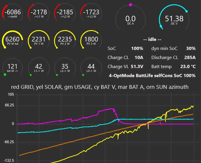
The Seplos sends a max. charge current limit (CCL) of 10A when a cell exceeds 3,5V.
In the attached picture you can see that the Systems recognize this but doesn´t react:
CCL is set on 10A but the ESS is charging with full power from the MPPT´s until the BMS cuts of.

Also: Whats wrong here? Is it a software problem or do i only have to adjust a setting?
(I guess Problem 2) and 3) have the same "root"...)


Thank you very much for your help!
Best regards
Leo

vrm-ccl-ohne-funktion.jpg


1 comment
2 |3000

Up to 8 attachments (including images) can be used with a maximum of 190.8 MiB each and 286.6 MiB total.

puitl avatar image puitl commented ·

For all following Seplos-Users with the same question:

With pulling up the following thread i get to the answer why it doesn´t work
https://community.victronenergy.com/questions/106290/bug-in-ess-dc-feed-in-enabled-charge-current-limit.html

Short summary:

Victron cannot reduce the charge current when charging from the solar chargers because of the risk of destabalize the system.

They recommend to reduce the end of charge-voltage (CVL) when single cell-voltages are getting to high


.

0 Likes 0 ·
ismalifepo4 avatar image
ismalifepo4 answered ·

I detect Seplos with a name (!)

can you change the name?screenshot-2022-07-20-22-04-55-835-nlvictronenergy.jpg


1 comment
2 |3000

Up to 8 attachments (including images) can be used with a maximum of 190.8 MiB each and 286.6 MiB total.

netrange avatar image netrange commented ·

Just go into the menu.

Should work, as with all other components!


0 Likes 0 ·
gregor avatar image
gregor answered ·

To allMake sure that you have the latest firmware installed on your Seplos BMS (Version 2.8)With the 2.8 the whole system is now running OK (CerboGC, 3ph MultiPlus, 3x4.8kW LiFepo4 15S)

batterydata2022-08-24-1.jpg

batterydata2022-08-24-2.jpg

batterydata2022-08-24-3.jpgbatterydata2022-08-24-4.jpg

batterydata2022-08-24-5.jpg

batterydata2022-08-24-6.jpg

batterydata2022-08-24-8.jpg


2 comments
2 |3000

Up to 8 attachments (including images) can be used with a maximum of 190.8 MiB each and 286.6 MiB total.

puitl avatar image puitl commented ·

Hi!

The older firmware was sending the value of "total voltage overvoltage protection" as CVL to the Inverter (what a nonsense)...how is it with the new firmware?

Can you set a extra charge-voltage (CVL)?

0 Likes 0 ·
hebs avatar image hebs commented ·

Would you be able to post a link to the 2.8 firmware please. I have 2.7 and cannot find the latest version. I really need to be able to measure cell imbalance from node red.


Thanks

0 Likes 0 ·
jeanmarie avatar image
jeanmarie answered ·

Hi @Puitl

haven't make tests but new firmware seems to take High pressure alarm - 1,00V as limit for CVL

CCL is now also calculated diferently : 1C instead of 0,5C

5 comments
2 |3000

Up to 8 attachments (including images) can be used with a maximum of 190.8 MiB each and 286.6 MiB total.

ds1707 avatar image ds1707 commented ·
Is it possible to get more data out of the CAN (voltage of each cell) and share it on mqtt?

I would like to get all the data into my home automation, and seplos does not share both CAN and RS485, that's why i would like to have all the data via CAN

1 Like 1 ·
jeanmarie avatar image jeanmarie ds1707 commented ·
with the latest firmware you know have the min and max voltage off all cells

don't think you'll be able to get more through the CAN link

You could use both CAN and RS485 at the same time but only to read data and not from the master battery (address=0)


1 Like 1 ·
kenzo avatar image kenzo jeanmarie commented ·
Make sure to ask support@seplos.com for this feature, I’d also like to see it (or at least for them to fix RS485 for all battery packs in CAN mode).
1 Like 1 ·
puitl avatar image puitl commented ·
Cool, that would be a little but fine progress^^
0 Likes 0 ·
jeanmarie avatar image jeanmarie puitl commented ·
Sorry, I was wrong, I made some tests this time and no, it's not the seplos setting that influence the CVL, don't know what it is
0 Likes 0 ·
rikhf avatar image
rikhf answered ·

Nice review, the latest BMS with Bluetooth:


2 |3000

Up to 8 attachments (including images) can be used with a maximum of 190.8 MiB each and 286.6 MiB total.

B H avatar image
B H answered ·

Hi All, I`m having a bit of problems connecting my Seplos bms to the GX device.

On the BMS: canbus Victron selected.

Connected the bms to the cerbo with a normal utp cable. (bms Canbus to Gx Ve-Can)

On the Cerbo:
Profile: Can-bus BMS (500kbits/s)
Network status :
State: Error-active TEC :0 Rec:0
RX : packets:32285, errors:12070


Does not show up in the devicelist on my Cerbo GX?

If i put the utp cable in the VeBus port, the multiplus trips and shuts down ?

Anybody have some tips for me plz ?

2 |3000

Up to 8 attachments (including images) can be used with a maximum of 190.8 MiB each and 286.6 MiB total.

jeanmarie avatar image
jeanmarie answered ·

As shown in many post about this subject, like this below for example, cable can't be a "normal" utp cable.

https://community.victronenergy.com/questions/144790/can-you-connect-a-seplos-bms-48v-100a-16s-directly.html

And don't forget also the adressing where the 4 first dip switches must be set to "Off" for the master battery

2 comments
2 |3000

Up to 8 attachments (including images) can be used with a maximum of 190.8 MiB each and 286.6 MiB total.

B H avatar image B H commented ·

Thank you , i will cut up the utp cable like this post:

"I wired the connection manually as follows:

SEPLOS CERBO SIGNAL

Pin 3 ----- Pin 3 GND

Pin 4 ------ Pin 7 CANH

Pin 5 ------ Pin 8 CANL

This works.

Wiring as per the SEPLOS manual does not work"

Let you know tomorrow if this worked for me !

It`s even in a victron manual <LINK HERE>

3.1 Type A

Function Victron VE.Can side Battery side
GND Pin 3 Pin 6
CAN-L Pin 8 Pin 5
CAN-H Pin 7 Pin 4
0 Likes 0 ·
der-neue-hier avatar image der-neue-hier B H commented ·
Buy a Typ A kable from Victron works
0 Likes 0 ·
cali-clim avatar image
cali-clim answered ·

Bonjour , si c'est un bms seplos E10 DERNIERE BMS ne pas modifier les dip !!!

2 |3000

Up to 8 attachments (including images) can be used with a maximum of 190.8 MiB each and 286.6 MiB total.

motylu avatar image
motylu answered ·

Hello,

I made a lot of PV installations with great Victron components using Pylontech batteries (US3000C or US5000) without any major problems.

Now I am trying this with Seplos batteries (2 pcs of PUSUNG-S - 100 Ah/5,12 kWh), but I have big problems starting from the beginning... Batteries has apparently the last firmware version 3.0 and I changed communication protocol to Victron. One module was purchased last year, the second in previous month.

First problem is compatibility with Victron communication protocol. Batteries sending to Cerbo GX all warnings/errors, charging voltage and allowed charging/discharging current. But no information about max. and min. cell voltages, temperatures, number of modules in parallel...

Second problem is that max. value of allowed charging/discharging current does not correspond to number of connected modules - the value is still the same, if there is connected only one or two modules...

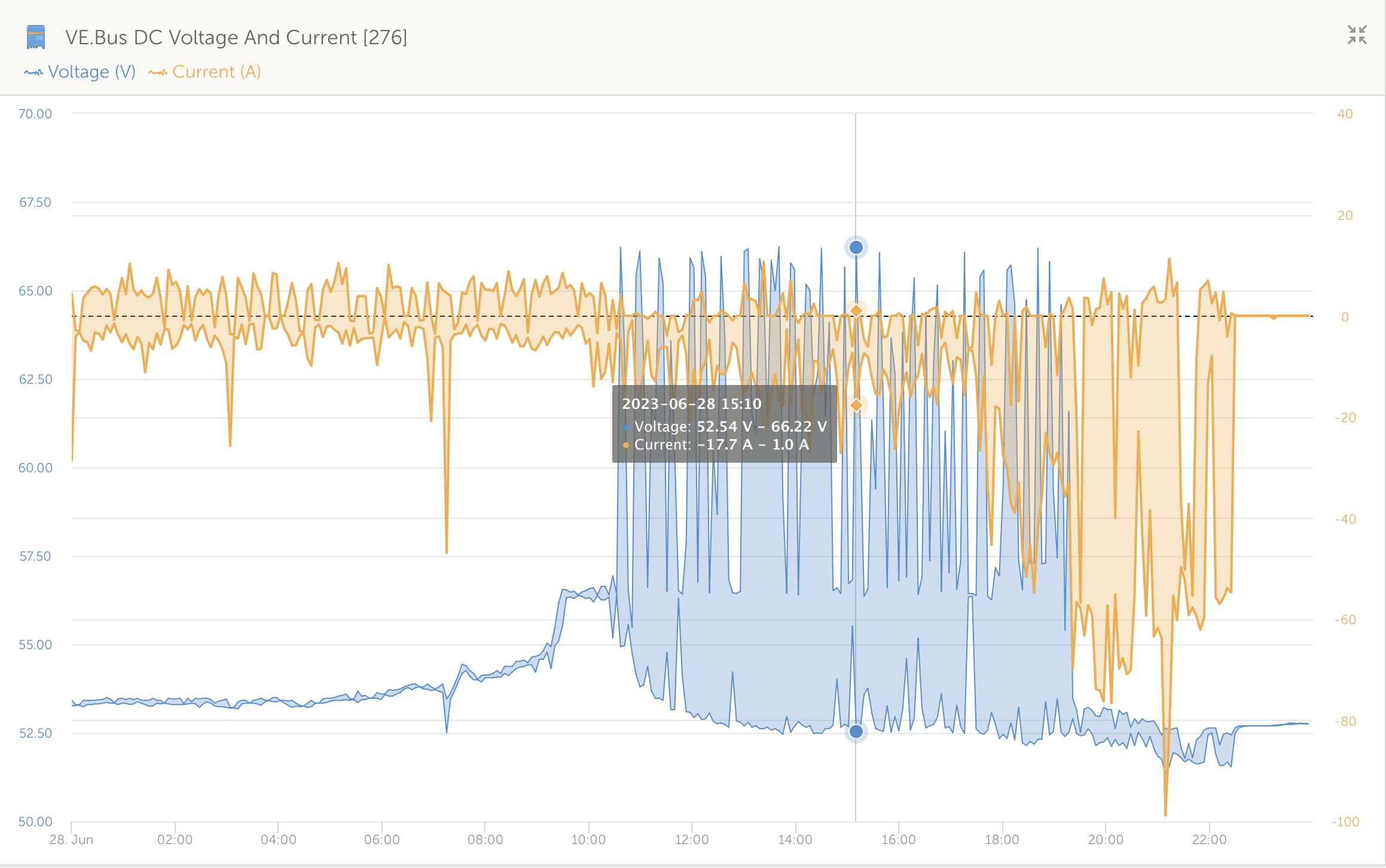
Third, but the biggest problem, is with charging voltage and behaviour of the BMS. The charging voltage sending from Seplos BMS is 58.4 V, the same value as high voltage alarm. This is the bad joke... So I must limit the charging voltage using settings in DVCC. I am testing charging limit gradually between 55.2 (3.45 V/cell) and 56 V (3.50 V/cell), but the batteries make the system very unstable. When batteries reached 100 % SOC they produce very high voltage peaks on the DC bus (in my opinion due to disconnection from the bus) and sometimes even causes errors of connected MPPTs (error #38 or #80).

Example:

snimek-obrazovky-2023-06-30-v212218.png


Does anyone have experiences with Seplos batteries with the latest firmware 3.0?

@P Fischer , @peterwolff , @Puitl , @jeanmarie , @cali-clim If you don't have problems with your installations, could you share your settings regarding the Seplos batteries - settings in Multis (Charge settings, Inverter settings, ESS settings - sustain and dynamic cut-off voltages), in MPPTs (absorption and float voltage) and Cerbo GX (DVCC)?

Many thanks for any help!


2 |3000

Up to 8 attachments (including images) can be used with a maximum of 190.8 MiB each and 286.6 MiB total.

jeanmarie avatar image
jeanmarie answered ·

Hi @motylu , sorry but I'm using the old BMS models (10C) and firmware are only going up to 2.9 but it is working well with several batteries in //.

Your voltage jumps are totally abnormal, I concede, but can't be caused by any battery (if voltage were that high, cells in the racks would be above 4V and therefor irremediably destroyed.

You should have one charger item in your configuration that is not operating in link with imposed voltage by the BMS through the CerboGX.

My voltage and adjustments are basics some 42V for cutt-off, 51V for sustain, 55.5/56.5 for float and absorption. and DVCC activated were I control the CVL voltage as for the firmware 2.9 CVL voltage is set at the maximum (58.2V). I also have problems, but only with AC-IN and, unfortunately for me, my problem doesn't seems to generate much interest, but that's the other side of the coin Victron, without being an expert in their product or being lucky to have an installer who knows products, pass by your installation every day and push Victron's hotline until all problems are solved then you can only try by yourself reading hundreds of page of document and trying, trying again ;).

I would say, as 1st diag, try fixing the communication issue, if you have 2 racks, the the master should send correct value to the Cerbo via BMS CAN, if it does not then it means the master BMS does'nt see the 2nd rack. In older BMS you must adjut the dip swith with the following logic : DIP1-4 = 0 for master, then 1 for the 2nr rack, 2 for the 3rd ...etc. and DIP5-8 used to define higher address of the connected rack, in your case must be set to 1 (dip5=ON)

Then check which item of your installation is sending such higher voltage, either a wrong parameter or a lack of CAN linking (or both)


7 comments
2 |3000

Up to 8 attachments (including images) can be used with a maximum of 190.8 MiB each and 286.6 MiB total.

motylu avatar image motylu commented ·
Hello @jeanmarie ,

thank you for your comments.

Now I am in close contact with someone from Seplos and I found from him, that after reaching 100 % SOC, the BMS sending 0 amps as allowed charging current but also disconnect batteries from the DC bus. And in my opinion, this is the whole problem, because battery disconnection produce current ripples and voltage spikes od the DC bus - I think MPPTs produce the voltage spikes.

I don't know the reason, why they disconnecting the battery, because for example Pylontech don't do this and of course there is no such kind of problem with the Pylontech batteries...

0 Likes 0 ·
jeanmarie avatar image jeanmarie motylu commented ·
mines are not behaving that way

do you know the model you have ? there are 10C (old BMS), also 10E (latest one with a new PCB and bluetooth ), maybe you have a new new model ?

On the 10C models with 2.9 firmware, when batteries are full (voltage > warning limit) then the CCL is set to 0 which order the Cerbo to stop charging but they are never disconnected totally.

Disturbance could occurs if your battery are not well balanced and one cell reach the disconnect limit with voltage / SOC being full. But even in such case, CErbo should receive the information "stop charging" and forward it to all charging devices in your installation.

You don't have external DC charger out of the Cerbo's control, don't you?


0 Likes 0 ·
motylu avatar image motylu jeanmarie commented ·

Hi @jeanmarie ,

I don't know the exact BMS version, but it has FW 3.0 and is not capable (verified with the distributor in the Czech Republic) to send details as min./max. cell voltage and so on. So there are probably some new new different BMSs :--(

I downloaded the data from both modules and sent to Seplos for analysis. I found, that there is lot of "Intermittent power supply waiting" warnings. About this warning there is a lot of discussions on the Internet and in my opinion this causing the voltage spikes on the DC bus, because BMS apparently (according to documentation and discussions) disconnect the battery by MOSFET, when reaches 100 % SOC and activate "intermittent power supply waiting" mode...

Now I am testing the installation again with two modules and limited charging voltage to 55.2 V and we will see. Maybe, I problems occur again, I will try to deactivate the "intermittent waiting" mode in the BMS settings for comparison.

0 Likes 0 ·
jeanmarie avatar image jeanmarie motylu commented ·

I have deactivated the "intermittent charging" option from the beginning.


Here with are my setting for my seplos BMS but as said above those setting are for the 10C model with 2.9 firmware (filename is for my personal versioning, nothing to do with firmware)Parameter 200A-16S_V3_0.xml


0 Likes 0 ·
motylu avatar image motylu jeanmarie commented ·
Thank you very much @jeanmarie for sharing your settings and of course information about deactivation of "intermittent charging"! I think, this function is the root cause of all problems...
0 Likes 0 ·
paf avatar image paf motylu commented ·
Hello @motylu, I have the same issue. My setup is 3x Multi 5000, MPPT RS 450, Cerbo and Seplos Mason 280. BMS.CAN from Seplos is connected and works fine with Cerbo.


The system runs fine when off-grid, but in ESS mode and feed-in enabled there are high DC voltage spikes when the battery disconnects. I have tried to lower the max charge voltage, but then the system is "overbalancing" the DC voltage by charging and discharging the battery to and from the grid very aggressively.


Did you find any solution? Thanks, Pavel.


0 Likes 0 ·
motylu avatar image motylu paf commented ·
Hello @paf .

Finally distributor of the Seplos batteries in the Czech Republic tested it and find the problem in the BMS. Now I am waiting, because Seplos is preparing some new firmware version for this another type of BMS installed in these batteries. In the meantime I disable "intermittent charging" function on all batteries, because this dramatically reduces voltage spikes to maximally one or two per two days.

1 Like 1 ·

Related Resources

EasySolar 1600 product page

EasySolar-II GX 3000 & 5000 product page

Additional resources still need to be added for this topic